 >
>


Product Overview of VIPER22AS by STMicroelectronics
The VIPER22AS represents a robust integration of control and power switching on a single chip, optimized for flyback-based switched-mode power supplies operating from an offline AC input. At its core, the device brings together a current-mode pulse width modulation (PWM) controller and a 730V avalanche-rugged power MOSFET, engineered on the same silicon substrate through proprietary VIPower™ technology. This integration enables efficient start-up and regulation without the need for external high-voltage transistors, inherently simplifying the overall bill of materials and layout. High-voltage startup circuitry, embedded protections such as over-temperature shutdown, overcurrent, and overload safeguards, as well as soft-start features, are provided on-chip to minimize external component count and streamline EMC compliance.
Operation within a flyback topology leverages current-mode control, which offers enhanced line and load regulation and fast transient response, critical for dynamically varying loads as encountered in consumer charging adapters and auxiliary bias rails. The peak current limitation implemented at the hardware level guarantees repeatable protection independent of variations in the external environment or aging of components—a key concern in practical deployments where regulatory and reliability standards are stringent.
The 8-pin SOIC package achieves space savings through reduced external circuitry and thermal dissipation optimization. Practical deployment consistently demonstrates that PCB layout becomes less sensitive to noise, and EMI optimization is more straightforward, as the critical high-voltage loop is confined within the package itself. In applications such as television standby power rails and compact motor drive auxiliaries, the VIPER22AS has repeatedly shown stable startup, minimal overshoot, and predictable behavior under brownout and fault conditions. Its burst-mode operation at light load reduces total standby consumption, directly meeting regulatory demands such as ENERGY STAR and lower ErP mandates.
One notable engineering observation is the device’s tolerance for input voltage fluctuations and fast recovery from short-circuit events. When implemented with adequately selected snubbers and feedback networks, the system reliably maintains output within specification even under severe line disturbances, providing resilience essential in geographically diverse deployments. This reliability directly supports long service life with reduced field failures, particularly in demanding environments with variable mains quality.
VIPER22AS’s design philosophy reflects a shift from discrete control and switching implementations toward highly integrated power stage solutions, minimizing assembly complexity while improving manufacturability. Its built-in protections and thermal shutdown circuits allow engineers to prioritize application-level innovation rather than basic survival circuitries. The device’s robust operation across wide input voltages and varied load profiles positions it as a preferred solution in mainstream SMPS segments, where cost, board area, and reliability must converge without compromise.
Key Features and Performance Characteristics of VIPER22AS
The VIPER22AS integrates key architectural elements aimed at reliable power conversion, offering design engineers a versatile solution for compact switch mode power supplies. The device’s fixed 60kHz switching frequency forms the basis for predictable electromagnetic interference (EMI) profiles, streamlining both filter design and compliance with regulatory standards. This attribute is particularly valuable when optimizing transformer size and minimizing the risks associated with variable-frequency spurious signals.
The extended VDD operating window, from 9V to 38V, introduces greater latitude in auxiliary supply arrangements. This flexibility simplifies adaptation across a diverse set of topologies—flyback, buck, or auxiliary bias circuits—mitigating the risk of undervoltage-related latch-up events or marginal start-up behavior. In application, this wide range minimizes the need for intricate supply sequencing or secondary voltage supervision.
Core to the VIPER22AS is an integrated current mode control strategy. By directly regulating the inductor current, the device achieves agile transient response and consistent loop stability, even in the presence of rapid load variations. This intrinsic current control not only enhances noise immunity but also simplifies overall compensation design, removing the layer of complexity associated with voltage-mode counterparts.
A multi-faceted protection suite is embedded to support robust field operation. The undervoltage lockout with hysteresis eliminates oscillatory start-up and shut-down cycles—a common pitfall in high-reliability environments. The high-voltage startup current source enables direct connection to rectified mains, reducing external component count and improving cold-start reliability. Overtemperature, overcurrent, and overvoltage protection mechanisms—with self-restart capability—ensure automatic recovery from fault events, reducing down time and enhancing safety-critical resilience.
The implementation of automatic burst mode operation at light loads directly addresses efficiency and thermal management targets. By reducing switching activity during stand-by or partial load operation, unwanted conduction losses and EMI emissions are significantly curtailed. Practical experience reveals a measurable decrease in auxiliary supply heat rise and improved standby power compliance in consumer and industrial power adapters.
The VIPER22AS exemplifies the trend toward high-integration offline PWM controllers with intelligent protection and adaptive efficiency enhancements. The device’s feature synergy—fixed frequency, wide VDD tolerance, current mode architecture, comprehensive protec-tion, and dynamic burst operation—marks a deliberate move away from legacy, discrete-intensive designs toward robust, application-agnostic platforms. Success in the field has demonstrated its reliable behavior under line harmonics and adverse thermal loading, affirming its position as a foundational element in modern auxiliary and low-power SMPS solutions.
Electrical and Thermal Parameters for VIPER22AS Design
Electrical and thermal characterization of the VIPER22AS directly affects design robustness and long-term reliability in power conversion systems. The device’s absolute maximum ratings—spanning voltage stress at the drain and control pins, as well as junction temperature—dictate safe operational boundaries. Specific attention must be allocated to the dual-state startup current source. When active, the inrush and dynamic capacitance charging events may cause transient overvoltage if input filtering is inadequate. Conversely, when inactive, startup surge is reduced but prolonged, risking insufficient bias for proper sequencing. Careful measurement and simulation of these startup profiles provide actionable insight for input cap sizing, snubber design, and pre-bias protection.
Thermal management pivots on accurate PCB layout and material choices. The SO-8 package’s thermal impedance, evaluated on a standard single-sided FR4 board with extended copper pour under and around the device, forms the foundation for dissipation calculations. Heat spreading effectiveness scales nonlinearly with copper area and trace thickness, and the optimum is rarely the datasheet minimum. Empirical validation—measuring package top temperature under maximum load and comparing with predicted junction temperature—ensures margin to the thermal shutdown threshold while exposing secondary hot spots arising from component clustering or compromised airflow. Derating strategies often emerge from such findings, balancing cost constraints with extended mission profiles in confined topologies.
Transformer design influences both electrical stress and thermal headroom significantly. Core size, winding configuration, and leakage inductance interact with the VIPER22AS’s switching profile to shape voltage ringing, turn-off losses, and overall system efficiency. Variations in line voltage and output loading demand meticulous validation across the full operational domain, avoiding edge-case violations of maximum voltage or current. Real-world data shows that conservative values for primary peak current and reduced transformer parasitics can improve electromagnetic compatibility and thermal balance without compromising dynamic performance.
Synthesizing these constraints leads to practical design patterns: paralleling PCB copper planes for better heat extraction, segmenting ground references to limit noise coupling, and sequencing startup with soft-start circuitry or controlled ramping. Such refinements are vital in applications ranging from compact chargers to white goods, where ambient conditions and load transients continually test the system’s limits.
Adopting an integrated approach, treating electrical and thermal limits as interdependent, not isolated constraints, fosters resilient designs. This systemic perspective anticipates field-driven failure modes and shapes proactive validation processes, marrying simulation with targeted prototyping. In this way, the full potential of VIPER22AS can be leveraged, translating device-level specifications into sustainable, manufacturable power solutions.
Functional Architecture and Control Principles of VIPER22AS
The architecture of the VIPER22AS centers on the synergy between an integrated PWM controller and a high-voltage power MOSFET, forming a compact topology that enhances both efficiency and design simplicity. The core control mechanism is based on current mode control, where an internal sense circuit derives a scaled representation of the MOSFET drain current during conduction. This proportional sense current enables real-time tracking of the primary current waveform, thereby delivering tight regulation and facilitating robust cycle-by-cycle current limiting. By leveraging current rather than voltage feedback at the designated feedback pin, the system achieves reduced response lag, improved line transient behavior, and inherent compensation against transformer parametric variations, all without sacrificing performance under varying operating conditions.
Thresholds within the circuit are governed by a precision internal voltage reference and an optimized resistor ladder, ensuring reproducibility of turn-on and turn-off levels independent of component tolerances and aging. This confers high accuracy to the mode transition and protection thresholds, key for safeguarding downstream loads and maintaining stability under load disturbances. Such granular current-domain feedback inherently simplifies transformer selection by decoupling the control loop from transformer magnetizing inductance and leakage effects, enabling use of off-the-shelf magnetics and expediting iteration cycles in prototyping phases. This design approach minimizes the propensity for subharmonic oscillations, a common setback in peak-current-mode topologies, especially under high input voltage or variable load regimes.
In practical implementations, the VIPER22AS demonstrates rapid dynamic response and mitigates the challenges often associated with loop compensation in primary-regulated offline flyback designs. Integrators observed that a wider tolerance window exists for snubber and clamp design, thereby broadening flexibility during EMI optimization and thermal management. This results in PCB layouts that are both compact and robust, reducing parasitics that are otherwise challenging to manage in discrete plus controller configurations.
The current-centric feedback method is especially advantageous in application scenarios requiring reliable isolation, such as auxiliary power supplies for appliance logic rails or low-wattage standby converters. These architectures benefit from the intrinsic simplicity in attaining Brownout, OVP, and output short-circuit handling, as all pivotal events are immediately reflected at the sensed current node. Deployment experiences confirm that stability and protection thresholds can be fine-tuned via straightforward resistor ratio adjustments, enabling rapid design turn-around and minimizing bench validation loops.
A distinguishing insight lies in the way the VIPER22AS manages lossless sensing and protection sequencing. The direct mapping of energy flow via drain current removes the ambiguity common in voltage-feedback schemes, offering a more deterministic response under both steady-state and fault situations. This approach carries through to improved EMI signatures and stretches the viable temperature operating envelope, a nuance appreciated during extended reliability qualification cycles.
By tightly integrating the control logic and switching device, the VIPER22AS delivers predictable performance, streamlines hardware iteration, and simplifies compliance with regulatory standards. Its operational philosophy, grounded in current domain feedback and precise thresholding, establishes a robust foundation for high-efficiency, reliable isolated supply designs across a spectrum of commercial and industrial applications.
Operational Behavior: Startup, Protection, and Burst Modes in VIPER22AS
The startup sequence in VIPER22AS leverages the high-voltage potential at the MOSFET drain to initialize system operation. Upon application of the input voltage, the internal circuitry directs current to the VDD capacitor, charging it progressively until the specified threshold is reached. At this point, the control logic enables the PWM switching function, orchestrated by a finely tuned soft-start algorithm to mitigate inrush and overshoot. The presence of an auxiliary winding substantially accelerates this process, stabilizing VDD more rapidly and allowing for consistent cold-start performance across wide input conditions. Conversely, insufficient bulk capacitance leads to erratic initialization, manifesting as delayed or failed startup cycles; tight attention to capacitance specification and board layout thus becomes critical for designers aiming for robust power-up behavior, particularly in cost-sensitive applications.
During continuous operation, the device maintains system integrity through layered protection schemes. The VDD overvoltage detection circuitry functions as a fast-response supervisor, monitoring supply rails and intervening upon transients that threaten both the switch and downstream components. When the VDD voltage surpasses its safety threshold, the controller executes a controlled shutdown—temporarily suspending switching—to dissipate excess energy and preclude overstress. Once conditions normalize, an automatic recovery sequence reinstates normal switching, ensuring minimal service interruption. Precision in threshold calibration and feedback loop design further enhances system resilience, reducing the risk of nuisance tripping and improving immunity against input surges and line disturbances typical in industrial environments.
The device intelligently adapts its switching behavior under low-load or standby conditions by entering burst mode. In this state, the control logic intentionally suspends pulse generation, allowing output regulation with intermittent switching cycles. This selective omission of drive signals dramatically reduces core losses and transformer heating, directly impacting energy efficiency and compliance with stringent standby power regulations. Engineers benefit from the inherent simplicity of implementing burst mode in VIPER22AS, as it requires minimal external intervention; however, practical experience reveals the necessity to fine-tune output capacitance and filter networks to maintain output voltage stability and avoid oscillation during load transitions. Subtle system optimizations—such as damping network insertion and careful snubber design—often yield quantifiable improvements in both acoustic noise and electric performance.
Integrating these operational and protection features within VIPER22AS exemplifies a modern approach to primary-side regulation. The interplay of startup mechanisms, supervisory thresholds, and adaptive burst cycles reflects a design philosophy centered on balancing robustness, efficiency, and manufacturability. The architectural choices in VIPER22AS, especially the synergy between hardware protections and adaptive control strategies, enable high reliability in demanding converter applications while streamlining design-in for both high-volume and specialty power supply projects.
VIPER22AS Feedback and Regulation Mechanisms
VIPER22AS integrates a current-based feedback mechanism that redefines regulation dynamics in switching power supplies compared to conventional voltage-controlled PWM architectures. Fundamentally, current-mode control interacts more directly with the power stage, measuring and utilizing primary-side current information. This setup, when implemented with feedback isolation such as an optocoupler, creates a communication channel between primary and secondary circuits, ensuring responsive and precise regulation. This approach allows for a multi-loop regulation strategy, where both output voltage and load current are manipulated to maintain system stability.
A key advantage arises from the resultant rectangular output characteristic, particularly relevant in battery charging applications. In practice, this means the converter delivers either a regulated output voltage or a capped output current, meeting the requirements of common battery charging profiles. For Li-ion cells, optimal charging mandates a dual-phase process—constant current followed by constant voltage. The VIPER22AS, combined with secondary-side analog feedback controllers like the TSM101, enables seamless mode transitions. The TSM101 interprets deviations in output, influencing the feedback loop to adjust energy delivery in real time, thus meeting tight tolerances required by advanced battery chemistries.
Current feedback’s influence extends to dynamic response and control boundaries. The feedback path sets the thresholds for linear regulation as well as transition points to burst mode operation in light-load scenarios. The device’s control logic interprets feedback amplitude and trajectory, modulating switching patterns to avoid subharmonic oscillations and maintain high efficiency at low loads. The precise design of the feedback network—component selection, bandwidth optimization, and compensation strategy—directly impacts regulation accuracy, transient response, and overall system reliability.
From a practical engineering standpoint, careful layout and component placement of the feedback circuit are critical. Minimizing loop area in the optocoupler path reduces susceptibility to noise and common-mode disturbances. Sourcing high-linearity optocouplers and calibrating the secondary-side reference ensure accurate current and voltage matching. During system testing, adjusting the feedback divider and reference thresholds fine-tunes regulation points, customizing burst mode entry to balance efficiency and audible noise.
Integrated current-mode control also supports robust fault detection and system protection. Because instantaneous current information is available in the feedback loop, overcurrent and short-circuit conditions are rapidly detected and contained. This enhances the safety profile essential in charger designs that interface with sensitive cells. Additionally, current-mode structures scale efficiently with output stages; parallel converters maintain current sharing with simplified interconnection, minimizing external balancing circuitry.
In summary, the VIPER22AS's current-based feedback and regulation architecture offers inherent advantages for precision-controlled power delivery systems. It extends beyond mere voltage regulation, providing a foundation for high-performance, flexible, and protected converter designs encountered in modern battery charging and auxiliary power supply applications.
Engineering Applications and Typical Use Cases of VIPER22AS
The VIPER22AS integrates a PWM controller with a high-voltage power MOSFET in a single package, forming the core of cost-effective, compact, and robust AC/DC converters for sub-15W applications. The device’s architecture embodies critical mechanisms such as current-mode control, leading-edge blanking, and frequency jittering, directly translating into enhanced EMI performance and load regulation. The internal startup circuit leverages the MOSFET's high-voltage capability to initiate operation from line input without bulky external resistors, reducing solution size and startup complexity. This, coupled with edge-triggered burst mode logic, enables extremely low power draw under light load or standby conditions, a decisive factor in meeting tightening standby power regulations.
In battery charging circuits, the dual loop regulation—constant voltage and constant current—simplifies the realization of precise, reliable charging algorithms, safeguarding the battery against both overcurrent and overvoltage conditions. The soft-start feature mitigates inrush currents, extending charger lifespan and providing smoother system behavior during power ramps. Field implementations consistently demonstrate that the VIPER22AS solution outperforms discrete switcher circuits in maintaining safety margins, particularly under dynamic line or load disturbances. The integrated protection set (OVP, OCP, OTP) activates swiftly and recovers automatically, an essential trait in unattended charging environments.
Motor controller designs benefit from the VIPER22AS’s robust input immunity and high-voltage startup. Auxiliary rails for control logic tap into the low quiescent consumption, ensuring minimal thermal footprint within often-constrained enclosures. Integrated brownout detection and short-circuit protection shield the controller from erratic grid conditions and load faults, proven to reduce return rates in variable field deployments.
Consumer electronics leveraging always-on features, such as smart standbys and sensor wakeup functions, attain ultra-low standby current by exploiting the VIPER22AS’s burst-mode operation and its deep sleep thresholds. The wide VDD range, from UVLO at startup to full-load operation, ensures stable output despite brownout events, alleviating nuisance resets or misbehavior typical with conventional self-biased topologies. Deployments in appliances and display logic circuits routinely highlight the combination of minimal BOM count and reliable, low-loss operation as a competitive advantage.
In industrial and embedded realms, power rail solutions based on the VIPER22AS benefit from the device's compact DIP-8/SO-8 package, facilitating high-density board layouts and simple heat sinking. The built-in protection suite reduces the reliance on external safety components, streamlining safety certification and product lifecycle maintenance. Notably, the device’s consistent performance in high-ambient-temperature, high-transient-noise environments underscores its suitability for mission-critical controls, remote sensors, and distributed instrumentation. A recurring observation is the ease with which EMI compliance is achieved, attributed to the device's low noise switching and jitter tactics, effectively reducing the iterations required during EMC testing phases.
Distinctive in the VIPER22AS application philosophy is the balance between integration and configurability. Designers can tailor feedback networks and compensation schemes to achieve tight regulation or fast transient response without resorting to complex controller ICs, fostering rapid prototyping and reducing time-to-market. The persistent trend across diverse applications illustrates that the VIPER22AS reliably delivers both regulatory compliance and system robustness, particularly where board space and efficiency are at a premium. This synthesis of implementation simplicity and protective intelligence defines its enduring popularity within demanding power conversion tasks.
Mechanical Dimensions and Package Information for VIPER22AS
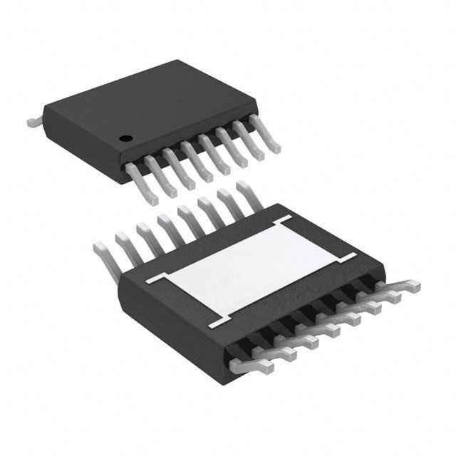
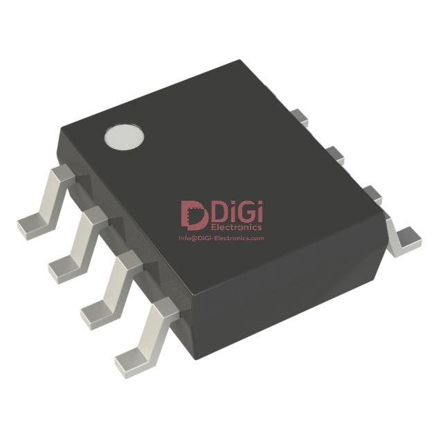
The VIPER22AS integrates seamlessly into standard PCB designs by adopting the industry-favored SO-8 package, which optimizes both physical footprint and thermal management for typical power conversion applications. Mechanical specifications for the SO-8 follow rigorous JEDEC MS-012AA outlines, ensuring precise lead spacing, pin coplanarity, and overall form factor consistency. These dimensional constraints guarantee compatibility with automated pick-and-place equipment, reducing variability during high-volume board assembly. The standardized body width and length enable predictable solder joint geometry and reliable electrical contact, directly supporting robust system integrity.
Availability in both tube and tape-and-reel formats aligns with scalable logistics for prototyping and mass production. Tape-and-reel packaging, governed by EIA-481 compliance, supports continuous feeding to SMT lines, minimizing downtime and manual intervention. This packaging flexibility expedites transition from small-batch validation to full-scale manufacturing, limiting process bottlenecks and optimizing supply chain responsiveness.
Uniformity in package dimensions facilitates drop-in upgrades for legacy designs, particularly where board real estate and pad layout are fixed constraints. The precise mechanical data allow for quick CAD library updates, streamlining revision cycles and reducing development risk. Electrical designers benefit from predictable parasitic behavior, thanks to tight tolerances in lead pitch and standoff height, which minimizes variability in signal integrity and thermal dissipation.
In practical deployment, leveraging the SO-8’s compact size expands integration possibilities in dense power supply topologies. Designs utilizing the VIPER22AS often exhibit improved electromagnetic compatibility due to minimized loop areas and consistent grounding schemes enabled by standardized pin orientation. Furthermore, the option to select between SO-8 and DIP-8 variants extends application scope to both surface-mount and through-hole environments, supporting rapid prototyping and legacy hardware maintenance.
This approach to mechanical standardization not only accelerates time-to-market but also reinforces long-term design flexibility, ensuring that as system requirements evolve, device adaptation remains low-risk and efficient.
Potential Equivalent/Replacement Models for VIPER22AS
Potential equivalent or replacement options for the VIPER22AS center on ensuring electrical compatibility, functional integrity, and mechanical fit within the target design. The VIPER22ADIP, designed by STMicroelectronics, stands out as a direct substitute, leveraging much of the same integrated offline converter architecture and supporting comparable input voltage ranges. While the core functionality remains consistent between VIPER22AS and VIPER22ADIP—critical for seamless integration—differences in package type must be closely examined. For example, the DIP configuration influences PCB layout, heat dissipation strategies, and assembly workflow, which can alter long-term reliability if not precisely matched to thermal management constraints.
Switching frequency remains a pivotal parameter in evaluating replacement suitability. Devices like VIPER22ADIP maintain similar operating ranges for switching frequency, preserving electromagnetic compatibility profiles and controlling transformer core losses in flyback topologies. However, subtle variances in oscillator tolerances or frequency jitter mechanisms between models warrant careful scrutiny; established experiential practice favors bench verification of switching waveforms post substitution to capture any deviation from the original spectrum, preempting EMI compliance issues and secondary side regulation drift.
Integrated protection features, such as thermal shutdown, overload management, and undervoltage lockout, are non-negotiable for robust converter operation. Engineers typically cross-examine the datasheets to verify that protection thresholds—in terms of current limit trip points and junction temperature cutoffs—mirror the VIPER22AS. Prior iterations exposed that mismatched protection settings can create vulnerabilities, especially under fault stress or varying ambient profiles. Experience attests to the tangible system impact when even minor changes in soft-start or auto-restart protocols occur, making bench simulation under worst-case fault loads a pragmatic step in the replacement process.
Feedback mechanisms, primarily driven by optocoupler interface and voltage reference accuracy, require confirmation of reference pin placement and output voltage tolerance. The subtleties of loop compensation and transient response hinge on this electrical congruence. Embedded reference design experience reveals that signal integrity across feedback pathways should be evaluated not just electronically, but also mechanically, especially when migrating between package types that modify parasitic capacitance or stray inductive coupling.
Pin-to-pin compatibility is the first barrier to physical swap feasibility. A successful substitution is predicated on maintaining identical pinouts and functional assignments. Deviation in thermal ratings between packages directly affects board-level thermal modeling; practical thermal imaging confirms that even 10–15°C differences in junction-to-case ratings can necessitate adjustment of heatsink dimensions or copper plane routing.
Ultimately, the nuanced selection of an equivalent model extends beyond datasheet comparison. The layered evaluation approach—from core architecture alignment, through protection and feedback coupling, to mechanical and thermal fit—sharpens the reliability of the final design. The principle of validating each replacement through environmental and electrical stress testing is consistently reinforced by field experience; only devices passing these real-world checks integrate seamlessly into commercial applications, avoiding latent failures and preserving system safety. This multi-dimensional scrutiny—rather than mere functional parity—forms the foundation for truly robust converter substitution when phasing in alternatives to the VIPER22AS.
Conclusion
VIPER22AS integrates high-voltage startup circuitry, current-mode PWM control, and comprehensive fault protection into a single compact package, creating a platform for streamlined, low-part-count SMPS architectures. The device’s 800 V avalanche-rugged power MOSFET allows direct connection to the rectified AC mains, enabling engineering teams to simplify input stages in designs targeting battery charger circuits, auxiliary rails, or standby supplies. A quasi-resonant operating mode minimizes switching losses, improving efficiency across light and heavy loads, an important factor in standbys governed by strict energy consumption regulations.
The built-in feedback system supports both primary and secondary regulation topologies, facilitating rapid adaptation to user requirements for tight voltage or current control. Error amplifier dynamics, as realized in VIPER22AS, provide stable loop compensation across varying input conditions and transformer tolerances, minimizing system drift and startup overshoot. These aspects are crucial when deploying solutions in environments where input voltages fluctuate or thermal variations are pronounced, such as industrial control panels or consumer appliance subsystems.
Abundant on-chip protection mechanisms—overload, overvoltage, over-temperature, and short-circuit resilience—reduce the likelihood of field failures, backing extended warranty claims and minimizing maintenance dispatches. The soft-start and auto-restart functions work cohesively to guard the power stage during fault recovery, while the controlled diode management limits EMI during repetitive transitions. In deployment, the lack of external startup bias circuits and the reduced PCB footprint facilitate rapid assembly and yield improvements, especially significant in cost-sensitive mass production.
From a sourcing standpoint, VIPER22AS offers cross-compatibility with several pin-for-pin alternatives, mitigating risk during supply chain fluctuations. This compatibility streamlines design upgrades without requiring extensive board re-layout, supporting longevity in hardware platforms where regulatory or market demands shift over time. Considering these factors when architecting the power stage ensures smooth transitions to future component iterations with analogous electrical performance.
Experience shows that rigor in transformer selection and keen observation of recommended PCB layout practices amplify the benefits of the device’s advanced features. Minimizing loop areas and adhering to proper grounding schemes directly impact EMI and thermal behavior, preserving reliability margins even in adverse installation conditions. When integrating VIPER22AS, iterative bench characterization under dynamic loads and ambient scenarios exposes areas for further optimization, fostering robust designs with minimal field diagnostics.
Selecting VIPER22AS streamlines low-power SMPS projects by converging essential safety, efficiency, and adaptability parameters into a single, field-proven device. Its architecture anticipates evolving regulatory and application needs, positioning it as a reliable baseline for both present and next-generation designs.