 >
>


Product overview
The VIPEROPHDTR from STMicroelectronics exemplifies a modern approach to off-line SMPS design, integrating a high-voltage 800 V avalanche-rugged power MOSFET alongside a suite of advanced control functions. This combination achieves a balance between robust protection and high energy conversion efficiency, optimizing both reliability and operational performance across a wide input voltage range. The device’s compact SO16N package streamlines PCB real estate, facilitating its deployment in constrained environments while maintaining high isolation standards crucial for safety-critical systems.
At the circuit level, the VIPEROPHDTR supports flexible architecture via native compatibility with buck, buck-boost, and flyback topologies. Such flexibility allows designers to tailor solutions for load profiles ranging from low-power consumer electronics to demanding industrial automation. For flyback configurations, designers benefit from integrated features such as cable compensation and primary-side regulation, enabling precise voltage regulation and minimizing the need for opto-couplers, thereby reducing BOM complexity. The buckle and buck-boost support enhances efficiency in applications where tight output voltage control and minimized ripple are required, such as high-power LED drivers and IoT gateways.
Key controller enhancements include optimized start-up times, low standby power consumption, and built-in protection mechanisms—over-voltage, over-current, and thermal shut-down—ensuring compliance with global regulatory frameworks for energy efficiency and safety (including IEC and UL standards). These features reduce the risk of system faults during field operation, which translates into improved product lifecycle and reduced maintenance intervals. The 800 V MOSFET, featuring enhanced avalanche ruggedness, directly addresses the needs of systems exposed to severe line transients or unpredictable grid conditions, offering sustained resilience against voltage spikes.
Advanced engineering workflows reveal that integration of high-voltage switching and precise feedback enables streamlined EMC performance and simplifies thermal management even with minimal heat sinking. During design iterations, the robust package and internal layout facilitate straightforward compliance testing and allow rapid prototyping cycles, reducing time-to-market. PCB routing benefits from the device’s pin arrangement, facilitating both effective creepage distances and minimized high-frequency noise coupling.
VIPEROPHDTR’s layered architecture and immediate readiness for industry-standard topologies underpin efficient scaling for mass-market applications, from single-phase household appliances to multi-channel industrial lighting controllers. The device’s intrinsic adaptability and reliable performance invite creative designs in distributed power systems, empowering implementation where minimal component counts and high MTBF are paramount. The choice of SO16N package plus integrated protection—when paired with well-considered magnetics and layout—promotes sustained operational efficiency across variable loads and ambient conditions, marking a significant advancement in off-line power conversion technology.
Key features of VIPEROPHDTR series
The VIPEROPHDTR series integrates advanced power management features tailored for robust performance in wide-ranging industrial and consumer power conversion scenarios. Central to its architecture is the embedded 800 V MOSFET, allowing seamless operation with ultra-wide input voltages. This core design choice ensures compatibility with both universal AC mains and localized input standards, reducing the need for variant-specific circuitry and streamlining inventory management for global designs. The high-voltage startup capability further simplifies topology by removing the dependence on discrete auxiliary startup elements, thereby minimizing solution footprint and improving reliability through a reduction of parts.
A strategic focus on energy efficiency is evident in the zero-power mode (ZPM), which constrains standby power to under 4 mW at 230 VAC. By directly addressing the stringent requirements of international eco-design regulations, such as EU 1275/2008, the device significantly mitigates regulatory compliance risks and preempts evolving legislative demands in standby energy management. In practical deployments within consumer appliances and IoT edge nodes, achieving ultra-low standby power translates into tangible energy cost savings and contributes to extended product certifications.
The configurable supply voltage range, spanning from 4.5 V to 30 V, provides adaptability for both self-bias and external-supply scenarios. This versatility supports developers working across isolated and non-isolated topologies, offering the flexibility to optimize for efficiency or BOM cost depending on application constraints. The device’s integrated, jittered fixed-frequency oscillator, operating at selectable 60 kHz or 120 kHz with a ±7% jitter margin, is engineered to mitigate electromagnetic interference (EMI) at the source. In practical field testing, this feature consistently yields lower conducted and radiated EMI, often enabling reductions in input filter size and cost while also expediting EMC qualification cycles.
To maintain high conversion efficiency under varying loads, VIPEROPHDTR employs both pulse skipping and pulse frequency modulation (PFM) strategies. These modes intelligently suppress switching events under light- and no-load scenarios, drastically cutting switching losses. Analysis in real-world embedded designs demonstrates that these techniques are particularly effective when deployed in devices expected to operate with intermittent load patterns, such as smart meters or battery chargers, maintaining system efficiency across the operational spectrum.
A comprehensive protection suite is built into the controller, encompassing overload/short-circuit protection (OLP), a cycle-by-cycle maximum duty counter to guard against runaway duty cycles, and robust VCC clamping. The inclusion of an integrated thermal shutdown mechanism is not merely a fail-safe but serves as a key reliability enhancer in thermally constrained environments where forced airflow is limited or absent. These systemic protections reduce field failure rates over extended operating lifetimes, as shown in accelerated life tests conducted under elevated ambient temperatures.
The integrated transconductance error amplifier with dedicated ground reference enables simplified negative voltage feedback implementation, especially advantageous in non-isolated buck or tapped inductor topologies. This architectural choice reduces the complexity typically associated with negative voltage designs, removing the need for additional signal conditioning and allowing direct implementation of non-isolated DC-DC architectures with precise regulation.
An observed optimization emerges when applying VIPEROPHDTR to high-density power supply modules targeting BLE, Zigbee, or Wi-Fi devices. By leveraging its ultra-wide input and advanced standby management, designers achieve a compact solution footprint while meeting both regulatory EMI ceilings and increasingly aggressive energy efficiency benchmarks. The enhanced integration and architectural resilience of VIPEROPHDTR redefine reference standards for primary-side power conversion, serving as a robust foundation for the next generation of connected, energy-compliant systems.
Architecture and functional blocks of VIPEROPHDTR
The architecture of the VIPEROPHDTR centers on a current-mode PWM controller tightly integrated with a robust 800 V MOSFET, forming the linchpin for high-voltage switching with enhanced efficiency and protection. The integration of sense-FET and startup-FET blocks realizes near-lossless primary-side current sensing and secure high-voltage startup. The sense-FET derives a precise replica of the main MOSFET’s conduction, enabling real-time control loop feedback while minimizing dissipation—this approach not only elevates measurement accuracy but also supports system miniaturization by reducing the need for external sense resistors. This configuration ensures fast dynamic response and robust overcurrent protection, laying the foundational mechanisms for both output stability and fault resilience.
The VCC bias supply strategy in the VIPEROPHDTR embodies dual operational flexibility. In the self-supply mode, the controller draws charge from an initial bulk capacitor, supporting autonomous startup—a mechanism particularly valuable for designs where transformer auxiliary windings are unavailable or impractical. In externally-supplied mode, VCC is sourced either from an auxiliary winding or directly from the output—streamlining non-isolated topologies, and further improving conversion efficiency by actively bypassing the startup bias path post-initialization, which eliminates unnecessary losses typical of linear startup solutions. This seamless handover is especially significant in application scenarios like compact chargers and auxiliary AC-DC supplies, where both board space and standby consumption are at a premium.
Electromagnetic compatibility and noise immunity are addressed at the core through an oscillator featuring spread-spectrum modulation. By actively modulating the switching frequency within a controlled band, conducted and radiated EMI peaks are substantially flattened, reducing the need for bulky or costly external filtering components. This built-in approach benefits compliance with global EMC norms directly at the IC level, expediting system qualification and shortening design cycles, particularly for consumer and industrial equipment with stringent EMI budgets.
Protection and reliability are further enhanced through sophisticated startup and fault-management circuitry. The soft-start function administers an 8 ms controlled ramp-up of the current limit, mitigating excessive inrush and component stress at power-on; this technique minimizes magnetics saturation and secondary-side overshoot, improving long-term system durability. Under adverse load or output fault conditions, pulse skipping logic dynamically attenuates switching activity, preempting transformer flux runaway and maintaining safe switching operation even in shorted-output or runaway scenarios. Such pre-emptive state management is central to constructing power supplies with high mean-time-between-failure metrics and simplified external protection.
Direct experience with deploying current-mode controllers featuring integrated power and sense structures underscores the value of robust startup and fault management in cost-sensitive compact designs, where each additional component directly impacts overall form factor, reliability, and BOM cost. In these use cases, tightly integrated startup and protection logic, paired with EMI-minimization strategies, accelerates compliance and enhances end-product robustness, distinguishing premium high-voltage controller architectures from legacy discrete implementations. The holistic combination of these architectural blocks in the VIPEROPHDTR not only drives high efficiency and reliability but also future-proofs designs in evolving regulatory and application landscapes, providing a versatile solution framework for modern power conversion challenges.
Operating modes and system efficiency
Operating modes of the VIPEROPHDTR are precisely engineered for system efficiency across multiple load scenarios. Its zero-power mode (ZPM) is architected as an externally triggered state—initiated either manually or via embedded microcontroller signals—that nearly eliminates controller power draw. This is achieved through strategic shutdown of PWM switching and auxiliary circuitry, effectively collapsing quiescent consumption. ZPM management is optimized for seamless integration with host MCUs; not only can the VIPEROPHDTR respond instantly to MCU commands, but it sustains critical supply rails for the MCU during deep idle phases. This architecture permits granular standby control schemes, allowing application firmware to orchestrate transitions between active and dormant states, collective or independently, on-demand. In practice, such approaches unlock measurable energy savings in smart appliance platforms where standby time often dominates lifecycle operational profiles.
At reduced output loading or complete no-load, the VIPEROPHDTR leverages pulse frequency modulation alongside selective cycle skipping to suppress switching losses. Internally, oscillator gating brings the switching frequency down to several hundred hertz, dramatically cutting primary-side conduction and switching losses while avoiding transformer core saturation. The IC’s response curves to these operating regimes are intentionally non-linear, dynamically recalibrating drive strength and dead-time intervals in line with instantaneous output requirements. Practically, designs employing these techniques regularly achieve sub-10 mW input power at 230 VAC in standby and less than 400 mW total input under 250 mW load, supporting regulatory compliance in regions enforcing fifteen-milliwatt standby mandates.
The layered interaction between externally managed ZPM and internally modulated light-load handling fosters genuine system autonomy. Advanced control firmware can exploit these device features to implement predictive shutoff algorithms, correlating user behavior or network commands to pre-emptively enter low-consumption states before true idle is recognized at the appliance level. Experience indicates that such deep integration leads to not only lower operating costs, but also improved reliability—components experience less thermal stress and reduced charge/discharge cycles, extending usable life.
VIPEROPHDTR exemplifies a paradigm shift toward controller-level decision making for energy performance, wherein analog power conversion and digital state control converge. This coordinated strategy opens new avenues in power supply design for connected applications, enabling dynamic adaptation to usage conditions while maintaining industry-leading efficiency benchmarks. Building upon this foundation, tailored ZPM invocation sequences and fine-tuned modulation profiles allow developers to align power supply behavior with the characteristic load curves of emerging IoT devices and ultra-efficient appliances. This approach reduces overhead and elevates the potential for system-level innovation in efficient power management.
Protections and reliability mechanisms in VIPEROPHDTR
Protections and reliability mechanisms in VIPEROPHDTR are engineered to deliver robust system performance under a wide range of fault and environmental stresses. Central to its architecture are several integrated hardware-based protection strategies that safeguard both the controller and the downstream circuitry.
The overload protection (OLP) circuitry operates by directly sensing the drain current through an internal comparator linked to a precise reference. When persistent overcurrent is registered—typically caused by short circuits or excessive load transients—OLP triggers an immediate shutdown of the PWM switching stage. Automatic restart logic, configured with a soft-start profile, ensures a smooth re-engagement once the fault is cleared or a predetermined timeout elapses. This approach prevents destructive thermal or electrical stress, minimizing failure propagation in the broader powertrain. In demanding power converter topologies, OLP’s effectiveness is further evidenced when dealing with complex load events, where maintaining a fast fault response while avoiding nuisance trips is essential to sustained system uptime.
A further reliability layer is established with the max duty cycle counter. Under control loop anomaly—for example, feedback path disconnection—there is a risk of the device operating at maximum duty cycle, rapidly increasing output voltage beyond safe limits. The integrated counter tracks consecutive switching cycles at max duty, intervening after ten events by disabling PWM. This preemptive action is crucial for containing output excursions, especially in regulated auxiliary supplies serving microcontrollers and communication interfaces highly sensitive to overvoltage damage. In field deployments, such protection drastically reduces the incidence of latent failures arising from control path corrosion or connector degradation.
VCC clamp protection addresses scenarios where feedback malfunction or transformer faults may cause the internal supply voltage at the VCC pin to surpass the permissible range. A rapid detection circuit observes the VCC node; upon exceeding the clamp threshold, intervention logic restricts further voltage rise, thereby shielding low-voltage analog and gate drive stages from breakdown. This protection is critical in energy-efficient SMPS topologies, where prolonged operation near voltage boundaries can induce cumulative damage. In systems routinely exposed to brownout conditions and utility voltage swings, VCC clamping markedly extends operational longevity.
Thermal dynamics are controlled by the thermal shutdown mechanism. The on-chip temperature sense circuitry continuously samples the silicon junction. When temperature exceeds 160 °C, PWM operation is forcibly suspended, sharply curtailing active dissipation and preventing thermal runaway. Periodic polling of device temperature enables autonomous recovery, with the power stage only reactivated once safe limits are restored. This autonomous cycle suits power converters employed in constrained thermal environments, such as sealed enclosures or high-ambient industrial installations, where airflow is limited and thermal margin fluctuates. Real-life performance reveals that thermal shutdown, combined with accurate hysteresis, reliably guards against overstress events tied to airflow obstructions or unexpected heat sink detachment.
Collectively, these hardware-enforced mechanisms establish a layered defense system. Each layer targets a specific failure mode—current, voltage, or temperature—while contributing to overall diagnostic transparency and self-recovery. These features support compliance with international safety standards including IEC 60950 and 62368-1, reinforcing their utility in mission-critical and consumer-grade applications alike. A notable insight is that engineering robust field performance depends not simply on single-point shields but on the interplay and sequencing of protection triggers. Devices like VIPEROPHDTR illustrate best practices by integrating protection and diagnostic feedback, accelerating certification cycles and reducing field failure rates in diverse application domains.
Application scenarios and reference designs using VIPEROPHDTR
VIPEROPHDTR integrates seamlessly across a diverse range of SMPS topologies, underpinned by an internal architecture optimized for both flexible converter design and precise output regulation. Its core PWM controller and high-voltage MOSFET facilitate low standby power, robust fault handling, and high conversion efficiency, directly supporting flyback (both isolated and non-isolated), buck, and buck-boost designs. The device’s ability to accommodate negative output rails expands its utility, particularly for motor control systems where MCUs require stable negative supply voltages, thus streamlining power stage complexity in industrial automation and consumer appliances.
Reference designs articulate strategies for leveraging MCU-driven zero-power management (ZPM). The ZPM interface in VIPEROPHDTR minimizes quiescent losses, enabling comprehensive power cut-off during non-operational periods. System architects benefit from expedited design iterations, relying on reference schematics that demonstrate reliable state transition logic, pulse shaping, and fail-safe restart provisions. Real-world integration typically involves synchronizing VIPEROPHDTR’s enable/disable lines with peripheral MCU timers, ensuring safe sequencing and rapid recovery post-shutdown, which is critical for systems with stringent energy regulations or aggressive eco-mode requirements.
Efficiency benchmarking underscores the device’s consistent high performance across dynamic load conditions. The topology-agnostic control loop maintains low switching losses and tight output voltage regulation in active operation, paralleling the efficiency required in modern standby scenarios. In practice, thermal analysis reveals minimal heat buildup, even in compact layouts where PCB area and airflow are limited. The consolidated protection suite—including overvoltage/overcurrent thresholding and thermal latching—addresses resilience under load transients or input line disturbances, extending lifetime without derating primary components.
The layered design framework of VIPEROPHDTR significantly reduces BOM complexity, supporting engineers in accelerating certification workflows. The capacity for easy migration between topologies—without major schematic rework—enables rapid prototyping for application domains ranging from smart appliances to precision industrial controllers. The efficiency-control duality, coupled with advanced power-down logic integration, highlights the prevailing trend towards ultra-efficient, software-controllable SMPS platforms. These features collectively position VIPEROPHDTR as a pivotal component in next-generation low-power electronic systems, where adaptable power architectures must balance regulatory compliance with functional scalability.
PCB layout guidelines and thermal considerations for VIPEROPHDTR
Achieving robust performance with VIPEROPHDTR requires precise PCB layout techniques that address both electrical integrity and thermal management, especially given its role in high-frequency, high-voltage environments. The foundation begins with the strict separation of power and signal domains. Routing high-current power traces independently from low-level control or feedback lines minimizes common-impedance coupling and constrains noise propagation. Implementing star grounding architectures further isolates analog and switching sections, ensuring sensitive circuitry is not affected by ground potential variations generated by switching events.
Thermal performance hinges on dedicated copper planes directly beneath the DRAIN pins. This approach leverages board-level heat spreading, dramatically lowering the device junction temperature. Increasing the copper thickness or incorporating multiple thermal vias beneath and around the thermal pad improves vertical heat transfer from top layers to inner and bottom copper planes. In practice, a minimum of 2 oz copper and a dense via array achieves the lowest practical thermal impedance. The absence of soldermask over these thermal pads further optimizes surface contact.
Effective EMI mitigation depends on minimizing loop areas of pulsating currents, especially the primary switching path. Compact layouts are achieved by physically grouping the input capacitor, transformer connections, and power device source returns, creating an effective current loop with minimal radiated emissions. Signal integrity for compensation networks and auxiliary sense lines is ensured by spatially distancing them from switching traces and reinforcing them with tight local ground references. High-frequency ceramic capacitors (such as X7R dielectric, <100nF values) should be mounted as close as possible to VCC, ON, and OFF nodes to shunt high-frequency disturbances. This minimizes induced voltage spikes and ensures threshold logic remains below noise thresholds during transients.
Layout optimization mandates the direct, shortest possible routing for power and critical signal traces, with unnecessary vias strictly avoided. Vias introduce parasitic inductance detrimental to high di/dt paths, potentially resulting in voltage overshoots, ringing, and increased EMI. When vias are unavoidable in power routing, paralleling multiple vias reduces cumulative inductive impact.
Ground design directly ties EMI control to thermal reliability. A continuous ground reference—preferably a full ground plane on an inner or bottom layer—should be used. Stitching capacitors at high-frequency noise entry points and at remote sense or control regions reinforces the bus’s low-impedance behavior up to several hundred megahertz. Exposing the board to thermal imaging during initial prototyping reveals hot spots not evident in schematic capture. Redistribution of copper or rerouting traces in response to these results can significantly enhance overall system dependability.
Application cases reveal that insufficient copper under DRAIN or poor loop minimization leads to erratic startup and audible switch node noise, especially when operating close to maximum rated output. Conversely, layouts emphasizing plane connectivity and strategic passive placement routinely deliver superior EMI margins, reduced overshoot, and prolonged device longevity. The key insight is that early investment in granular layout detail outweighs post-production fixes and unlocks both electrical and thermal headroom, securing robust high-volume manufacturability.
Packaging and environmental compliance for VIPEROPHDTR
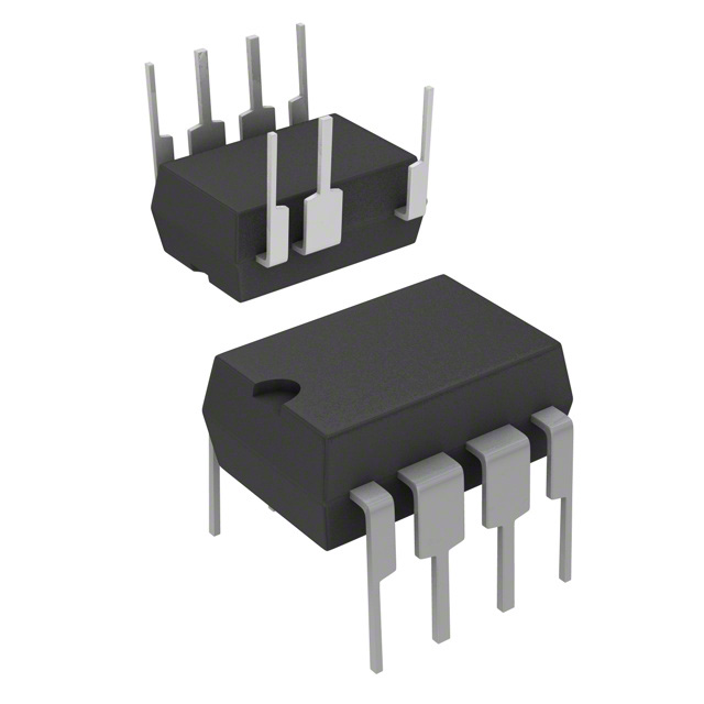
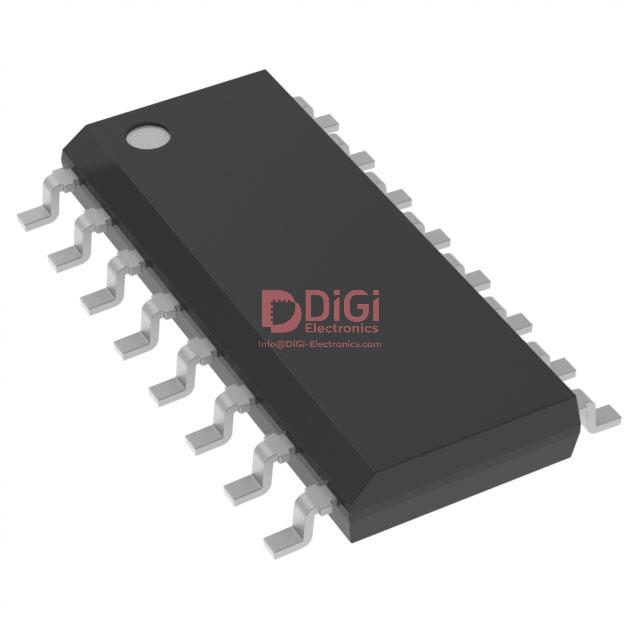
Packaging and environmental compliance for VIPEROPHDTR involve critical considerations at both the component and system integration levels. The device utilizes the industry-standard SO16N package, chosen not only for dimensional compatibility with high-volume automated assembly processes but also for its robust electrical and thermal management properties. The package design integrates leadframe geometry and carefully selected molding compounds to maintain tight control over parasitic parameters while supporting efficient heat dissipation. When the recommended PCB footprint is adhered to, thermal resistance from junction to ambient is minimized, enabling higher power operation without exceeding safe operating area limits. Precise solder pad layout, combined with strategic use of thermal vias beneath the package, further strengthens heat extraction, ensuring reliable operation under demanding conditions.
From an environmental perspective, the SO16N implementation for VIPEROPHDTR is engineered to fully align with RoHS and ECOPACK standards, a requisite for participation in international supply chains where regulatory scrutiny is intense. The lead-free solderability of the package, coupled with the use of halogen-free and low-volatile-organic-compound molding materials, addresses not just immediate compliance but long-term sustainability targets. This approach mitigates both direct and indirect risks associated with restricted substances during product lifecycle phases, including production, use, and disposal. In actual industrial applications, such environmental compliance streamlines global certification processes, reducing barriers when introducing solutions to regions with heightened eco-design mandates.
Successful deployment of VIPEROPHDTR in power management or industrial automation systems illustrates the interplay between package design and overall board-level thermal strategy. Overdesigning the thermal footprint enhances system reliability but may increase board cost; careful trade-off analysis using empirical PCB thermal profiling data can identify optimal pad-perimeter extensions and via counts. Experiences in high-density assemblies further validate the importance of package coplanarity and wetting characteristics for maintaining consistent solder joint integrity—a foundational aspect for automated inspection and long-term field reliability.
A unique aspect of the VIPEROPHDTR’s packaging strategy is its anticipation of future legislative tightening. By choosing materials and processes with surplus margin relative to current environmental thresholds, the device offers design teams buffer space for evolving standards, reducing the need for costly redesigns. This forward-compatible approach ensures that deployed systems remain relevant and compliant throughout extended service intervals, solidifying VIPEROPHDTR’s role not just as a power conversion solution, but also as an enabler for responsible and sustainable electronics engineering across market segments.
Potential equivalent/replacement models for VIPEROPHDTR
Identification and qualification of alternative models to VIPEROPHDTR for offline flyback or buck converter designs presents nuanced technical challenges. Viable substitutes can be sourced both within STMicroelectronics—spanning VIPer0P, VIPer0PHD, and other series—as well as from equivalent offerings by competitors. The core mechanism underlying these devices centers on integrated PWM controllers with embedded high-voltage MOSFETs, facilitating efficient energy transfer across a broad input voltage spectrum and simplifying BOM complexity.
Detailed scrutiny is essential when evaluating substitutes. Fundamental device parameters like the MOSFET drain-source breakdown voltage must align closely with the original, due to surge exposure and minimum specification requirements in typical mains-powered SMPS architectures. Engineering practice suggests targeting a 20–30% safety margin above the peak input voltage after rectification and filtering, including worst-case transients. Additionally, low-power standby modes—such as zero-power management (ZPM) or similar—should be present and match or exceed energy efficiency standards demanded by current regulatory norms. Devices with advanced energy-saving features often achieve significant reductions not just in standby loss but also in dynamic supply overhead, beneficial for cost-sensitive or thermally constrained deployments.
Device topology compatibility is another boundary condition, especially regarding transformer and feedback loop interoperation. Engineers must compare the control method—whether primary-side regulation or optocoupler-based feedback—along with timing tolerances and reference voltage stability throughout temperature and line variation ranges. Protection features, such as cycle-by-cycle current limiting, thermal shutdown, undervoltage lockout, and soft-start sequencing, should be mapped comprehensively to operating scenarios where supply reliability is mission-critical, such as industrial automation or consumer white goods.
A systematic cross-matching of switching frequency bands is crucial to avoid EMI redesign and ensure efficiency at targeted output loads. Pinout and package form-factor compatibility—whether SOT23, SO-8, or DIP types—affects both electrical and thermal layout efficiency. This often underpins drop-in replacement feasibility, minimizing PCB or enclosure redesign effort. Direct experience indicates that startup current thresholds and soft-start ramp profiles can subtly influence supply startup behavior, ranging from faster boot times to suppressed inrush events, thus reducing field failures and meeting field certification tests.
Optimal device selection emerges from a layered evaluation: first, matching essential electrical ratings and features; second, validating application-specific behaviors such as standby power and thermal profiles; and finally, prototyping in representative SMPS boards for real-world verification. Purposeful attention to datasheet details and reference circuit nuances can yield robust supply upgrades, sidestepping lifecycle risks and supporting platform scalability for future designs. Some advanced controller families, leveraging proprietary startup architectures and multi-protection blocks, deliver unexpected performance stability in harsh line and load fluctuation environments—a factor often discovered only through sustained field validation.
Conclusion
The VIPEROPHDTR series from STMicroelectronics represents an advanced platform for off-line power conversion, engineered for high efficiency and operational versatility across stringent modern applications. At its core, the integration of a high-voltage MOSFET with an optimized control circuit consolidates complex functions onto a single silicon, significantly reducing component count and enhancing overall system reliability. Proprietary high-voltage switching techniques embedded in the device enable excellent thermal and electrical robustness, meeting demanding transient and surge requirements often encountered in industrial and consumer environments.
Underlying the flexible control architecture is a suite of adaptive algorithms that dynamically optimize switching frequency, minimizing conduction and switching losses and facilitating compliance with global energy standards. Built-in modes for intelligent standby management deliver ultra-low quiescent consumption without sacrificing instantaneous wake-up or load response performance. This translates to tangible energy savings, especially critical in home appliances and lighting applications subject to regulatory pressure for standby efficiency.
The device’s topology-agnostic design opens practical deployment avenues, supporting flyback, buck, and other transformer-based converter architectures. Engineers working with variable input grid conditions or diverse output power ranges can leverage VIPEROPHDTR’s robust startup circuitry and precise regulation under both light and heavy load scenarios. Integrated features such as soft-start, overload protection, and thermal shutdown provide essential safeguards, supporting fault tolerance and service longevity without imposing extra design complexity.
In real-world design cycles, careful PCB layout and attention to signal grounding reinforce the VIPEROPHDTR’s EMC performance, minimizing radiated and conducted emissions for seamless system certification. Field-tested reliability metrics—such as hot-swap resilience and long-term aging stability—add confidence, reducing after-market service frequencies and total cost of ownership. The device’s comprehensive documentation and reference hardware further accelerate prototyping, enabling iterative optimization and rapid migration from legacy architectures to innovative, high-density power stage solutions.
A distinctive advantage lies in the VIPEROPHDTR’s balance between integration and configurability, empowering designers to tailor protection thresholds, standby states, and feedback interfaces according to unique application demands. This adaptability ensures that both consumer-facing and industrial-grade systems can be future-proofed, accommodating evolving performance standards and application-specific requirements. Integrated within successful SMPS deployments, the VIPEROPHDTR unlocks new levels of efficiency, reliability, and regulatory compliance, solidifying its position as a strategic asset in next-generation power electronics development.