 >
>


Product overview of VIPER16LD STMicroelectronics IC OFFLINE SWITCH MULT TOP 16SO
The VIPER16LD integrates fundamental building blocks for offline switch-mode power conversion, enabling compact and reliable circuit design in environments demanding tight efficiency and robust operation. At its core, an avalanche-rugged 800V MOSFET is tightly coupled with a PWM controller, forming a monolithic solution that minimizes external component count and simplifies board layout—critical advantages where PCB space and BOM cost constraints predominate.
The device’s internal PWM engine supports multiple conversion architectures, including buck, buck-boost, and primary-side flyback, offering versatility across both isolated and non-isolated power rails. This flexibility allows for streamlined adaptation in systems ranging from appliance auxiliaries to smart metering equipment. The fixed 60kHz switching cadence, complemented by implemented frequency jittering, mitigates peak EMI, facilitating straightforward pass-through of international EMC standards. Experience shows this approach substantially reduces filter footprint and cost, a beneficial trait in iterative design cycles striving for regulatory compliance without excess overhead.
Low standby power is aggressively optimized—under 30mW at 230VAC—enabling energy-efficient performance in always-on or ultra-low-load contexts, which is a non-trivial requirement for modern eco-regulations and standby consumption mandates. Such characteristics make VIPER16LD particularly suitable for applications in LED drivers and the modernization of legacy capacitive supply networks, where lifetime reliability and drop-in compatibility matter.
Thermal management and surge resilience are enhanced by the high-voltage MOSFET, validated under conditions of grid transients and fault scenarios commonly encountered in industrial and consumer electronics deployment. Real-world application demonstrates stable operation across diverse line voltages, with the narrow SO16 package maintaining mechanical compatibility in dense, automated assembly lines. This packaging also simplifies integration into modular designs, lowering the barrier for rapid prototyping and revision cycles.
A key insight for successful implementation is leveraging the device’s operating envelope for both primary-side regulation and transformerless supply designs, maximizing adaptability toward evolving power requirements. Circuit-level experimentation reveals that judicious choice of external feedback and snubber components yields consistent output precision and prolonged lifecycle, especially in applications prone to voltage sags or surges. The inherent over-current and thermal protection mechanisms further contribute to system robustness, reducing the necessity for external safeguard circuits.
Overall, the structural integration and operational features of the VIPER16LD are tuned for engineers prioritizing total cost of ownership, layout simplicity, and compliance confidence, making it a cornerstone for resilient, next-generation offline SMPS architectures.
VIPER16LD functional architecture and application versatility
The VIPER16LD employs a monolithic architecture that integrates a high-voltage startup circuit with current-mode PWM control, resulting in a robust platform for off-line SMPS implementations. Its ability to connect directly to rectified mains through an embedded avalanche-rated power MOSFET streamlines input stage complexity, especially in compact or cost-sensitive power designs. This eliminates the external startup bias requirement in low-power scenarios, reducing both component count and PCB footprint.
At the control level, the PWM core supports both fixed and variable frequency operation, enabling precise output voltage and current regulation across a wide range of applications. The device’s versatile feedback interface, realized via the FB and COMP pins, allows seamless adoption of voltage-mode, peak current-mode, or quasi-resonant control schemes. Such adaptability supports multiple topology implementations, including buck, buck-boost, and flyback configurations. In buck mode, direct step-down converters can be achieved with minimal external circuitry, suiting LED drivers or auxiliary low-voltage rails. Buck-boost mode addresses scenarios with varying line conditions or inputs near desired output levels, common in industrial sensor powering. Flyback implementations, with support for isolated or non-isolated outputs, simplify norm-compliant SMPS designs for appliance and metering sectors, where safety isolation is paramount.
Integrated protection and soft-start routines are foundational in enhancing circuit reliability and system robustness. The inrush current at power-up is managed by a finely tuned soft-start algorithm, easing stress on both the switching element and downstream circuitry. Furthermore, the chip features built-in over-temperature, overcurrent, and overload protections, ensuring resilient operation even under abnormal load or line conditions. The self-biasing mechanism, activated after initial turn-on, maintains control supply without auxiliary windings, maximizing efficiency in standby and active states. In designs where input power draw minimization is critical, such as IoT edge devices or compact household electronics, these attributes contribute to meeting stringent energy regulations.
Engineering practice reveals that the VIPER16LD's compactness and flexibility facilitate rapid prototyping and streamline certification efforts. The reduction in design iteration cycles stems from minimized dependency on external auxiliary supply windings and the straightforward integration of EMI compliance measures, made easier with the device’s controlled switch transitions. Employing the VIPER16LD accelerates the transition from concept to volume production, notably in space-limited or multi-variant platforms. Its single-package approach not only reduces sourcing and logistics complexity but provides a consistent performance baseline across applications, thus supporting scalable and modular power architectures.
An analysis of field deployments indicates that the architectural choices within the VIPER16LD directly impact long-term operational reliability. The combination of intrinsic protection logic and optimized startup behavior reduces RMA rates associated with overstress failures and startup misconfigurations. The device’s capacity for topology reconfiguration encourages design reuse, decreasing total cost of ownership and engineering overhead in systems where diverse supply topologies are required across a product line.
In summary, the VIPER16LD exemplifies a convergence of integration, control sophistication, and layout efficiency. Its modular support for switch-mode topologies, coupled with advanced protection and low-component-count operation, positions it as a cornerstone for modern off-line power management solutions where adaptability and reliability are paramount.
Electrical characteristics of VIPER16LD STMicroelectronics IC OFFLINE SWITCH MULT TOP 16SO
The VIPER16LD from STMicroelectronics functions as a highly integrated offline switcher IC, engineered for robust and efficient operation in universal AC line environments. At the device’s core lies an 800V-rated n-channel MOSFET, which endows the system with the requisite surge immunity for global input ranges, including brown-out and line transients. Its on-resistance, specified at 20Ω typical, strikes a calculated balance between switching efficiency and device ruggedness, mitigating conduction losses while keeping the die area compact to control parasitic capacitances. This attribute is especially important under light load conditions, where primary-side conduction losses threaten to predominate.
The adjustable drain current limitation framework is a central aspect of application flexibility. Through the LIM pin, system designers introduce an external resistor to precisely modulate the current threshold, thus matching the device’s overcurrent response to transformer sizing or fault tolerance strategies. Internal characterization curves, such as drain-current limit deviation over temperature and with varying LIM resistor values, are indispensable during circuit prototyping—especially when derating margins must be guaranteed under worst-case ambient or aging. Current limiter accuracy ensures downstream protection, preventing magnetics saturation or rectifier failures during abnormal events. In EMI-conscious applications, such as power adapters or industrial control modules, fine-tuning this setpoint reduces stress-induced ringing and diminishes the need for expensive oversized magnetic components.
The PWM switching core operates at a stable 60kHz, subject to a factory-trimmed ±4kHz frequency jitter scheme. This minor modulation is a deliberate mitigation technique, scattering electromagnetic emission peaks to meet stringent emission masks without resorting to heavy and costly filtering blocks. The inherently low operating supply current is key to maintaining high efficiency, especially in standby and no-load scenarios common in IoT endpoints, submetering, and battery charger designs. This feature is synergistic with power consumption regulations, such as EU ErP or DOE Level VI standards, that necessitate ultra-low standby losses.
Thermal management is handled by the IC's built-in temperature monitoring and shutdown. Hysteresis in the shutdown circuitry prevents oscillatory restart behavior, providing controlled recovery. This mechanism is vital when operating at higher ambient temperatures or in highly compact enclosures, where convection is minimal and thermal impedance is significant. Deployment experience shows that tightly coupling the VIPER16LD thermal pad to generous PCB copper pours can extend safe operating margins.
Analyzing internal parameter interdependencies is advantageous during system optimization. For example, as junction temperature increases, the MOSFET’s on-resistance rises, impacting both conduction losses and drain current limit reproducibility. Utilizing the documented graphs allows a predictive assessment—guiding the decision on whether secondary-side redesign or snubber adjustments are preferable for a given thermal envelope and protection target. Practical fine-tuning often emerges at this interface, where empirical bench measurements validate simulation models against real-life drift in breakdown voltage or current shaping.
The net result is a device that combines configurability, protection, and EMI-conscious design into a single package, streamlining the design of power solutions that must fit stringent size, efficiency, and regulatory envelopes. Emphasis on the adaptive drain current limitation, the calculated approach to EMI mitigation, and built-in thermal robustness coalesce to offer both predictable and flexible performance in demanding offline switching power supply applications.
Power section design in VIPER16LD STMicroelectronics IC OFFLINE SWITCH MULT TOP 16SO
Power section design for the VIPER16LD employs a highly integrated n-channel MOSFET, configured for avalanche operation. The device architecture incorporates extensive avalanche ruggedness, with transient immunity up to 800V. This elevated voltage tolerance is achieved through advanced trench optimization in the MOSFET fabrication, combined with precise silicon layout techniques that mitigate stress concentrations during overvoltage events. Avalanche capability ensures dependable operation under line surges and inductive flyback scenarios, a critical requirement for offline switch-mode power supplies exposed to fluctuating grid conditions or poorly damped transformer windings.
Central to the VIPER16LD's current control is the adoption of a SenseFET topology, which utilizes a dedicated sense cell embedded within the power MOSFET die. This structure extracts a proportional replica of the main channel current, enabling lossless cycle-by-cycle sensing. Compared to traditional shunt resistors or discrete current transformers, this approach eliminates resistive losses and simplifies PCB layout by reducing bill-of-materials complexity. The inherently accurate current information supports reliable output voltage regulation in flyback and forward converter designs, while facilitating robust peak current cutoff and short-circuit protection. SenseFET integration allows real-time feedback without introducing latency or secondary artifacts, improving system stability especially under dynamic load transitions.
The gate driver subsystem is meticulously designed to balance performance and electromagnetic compatibility (EMC). By precisely shaping both the rising and falling edges of the gate waveform, the driver minimizes dv/dt-induced common mode noise—a primary source of EMI in high-frequency switching environments. Gate resistor networks are dimensioned to optimize turn-on/off times without degrading switch efficiency, and internal Miller clamp circuits suppress parasitic oscillations that often plague compact offline converters. Such careful EMI control is paramount in meeting stringent regulatory standards, including CISPR and EN550xx compliance for both residential and industrial installations.
During undervoltage lockout (UVLO) events, internal logic vigilantly monitors the supply rail and disables gate drive when voltage dips below the threshold. The MOSFET remains actively biased in the off state, blocking conduction even as input fluctuations occur. This proactive measure protects the converter from spurious turn-on, latch-up, or thermal runaway conditions, complementing external fault monitoring and ensuring operational integrity across the entire load curve.
Empirical evaluation demonstrates that the VIPER16LD maintains stable switching performance across wide input ranges and variable load profiles. The fast response of the integrated current sensing loop enhances transient rejection and facilitates compliance with coordinated inrush and overload protection strategies. Design efforts further reveal that leveraging the internal gate driver architecture allows for reducing external EMI filters and shrinking overall converter footprint, promoting system-level miniaturization. From an engineering standpoint, the harmonious integration of rugged MOSFET construction, precision current sensing, and advanced gate drive forms a resilient backbone for demanding offline power supply applications, where reliability and electromagnetic hygiene are non-negotiable.
Control and protection features in VIPER16LD STMicroelectronics IC OFFLINE SWITCH MULT TOP 16SO
The VIPER16LD IC integrates a suite of control and protection mechanisms, forming the backbone of reliable offline converter topologies. At its core, a tightly controlled internal oscillator operates at a fixed 60kHz, with spread-spectrum modulation directly embedded to curtail electromagnetic interference. This approach not only steers system-level EMI below regulatory thresholds but also enhances immunity to external electrical disturbances, a decisive factor in maintaining stable converter function in noisy industrial environments.
Soft start circuitry forms a critical layer in safeguarding both magnetic elements and downstream components during startup. By moderating the initial drain current ramp, the IC mitigates excessive di/dt stress, rendering transformer saturation improbable and allowing passive filtering networks to settle without voltage overshoot. Utilizing adjustable current limit, set via an external RLIM resistor, designers can precisely define the converter’s maximum allowable drain current, which directly correlates to both device longevity and system safety. Controlled current capping, in practical circuit implementation, prevents excessive thermal loading and ensures that even under fault or overload conditions, the integrity of power switching components is preserved.
The feedback architecture is engineered for high versatility. The FB pin supports direct output sensing or scaled feedback for non-isolated configurations, enabling tight output regulation with minimal latency. For isolated topologies, the COMP pin provides a well-defined access point for compensation networks and opto-coupler input, streamlining the integration of secondary-side controls. This dual-path feedback design supports both high-efficiency optimization and robust fault signaling, making the converter adaptable to diverse design requirements, from consumer electronics to industrial control.
During periods of minimal load demand, burst mode operation activates, markedly reducing switching frequency and quiescent current consumption. This yields notable improvements in standby efficiency—a key driver in meeting stringent energy consumption standards. In practical deployment, burst mode also suppresses audible transformer noise, particularly in appliances sensitive to sound emissions. The seamless transition between normal and burst modes ensures that output voltage ripple remains within specification, maintaining device performance across all conditions.
Protection systems are multi-tiered. Auto-restart functionality dynamically recovers from acute fault scenarios such as output short-circuit or overload, introducing controlled restart pauses which reduce long-term device stress. The open-loop protection algorithm offers nuanced diagnostic capability, distinguishing between transient feedback disruptions—such as connector faults—and more endemic failures in magnetics or layout. By forcefully clamping output and instigating controlled shutdown, the IC preempts unsafe voltage excursions, shielding both the load and upstream supply.
From a system integration standpoint, the consolidated control and protection features of the VIPER16LD reduce peripheral complexity, accelerate compliance with international safety and EMC regulations, and streamline qualification cycles. Design iterations benefit from the inherent consistency of fault management and loop control, allowing predictable converter response under a wide spectrum of operating and fault conditions. The ability to tightly define operational boundaries, coupled with self-recovery capabilities, establishes the VIPER16LD as a reference for robust, high-reliability switch-mode power supply architectures. A notable insight emerges: embedding these layered mechanisms within a single IC not only elevates fail-safe performance but also simplifies board-level design, enabling rapid adaptation across application domains with minimal modification to core circuitry.
PCB layout guidelines for VIPER16LD STMicroelectronics IC OFFLINE SWITCH MULT TOP 16SO
Optimized PCB layout is foundational to the high-efficiency operation of the VIPER16LD offline switcher, directly influencing both electromagnetic interference characteristics and thermal performance. The grounding structure deserves particular attention; isolating signal and power grounds mitigates parasitic coupling and reduces susceptibility to high-frequency switching noise, with a single-point ‘star’ ground near the IC meticulously controlling return paths. This approach prevents circulating currents that might introduce voltage offsets at sensitive control nodes, ensuring signal integrity even as converter topologies become more complex.
The spatial arrangement of primary and secondary pulsed loops directly affects the electromagnetic field distribution. Minimizing these loop areas constrains both radiated and conducted emissions, a prerequisite for meeting stringent EMC regulations. On practical layouts, the main switching node and its return must be placed adjacently, often by folding the high-frequency loop over a local ground plane when possible. The shortest possible connection between compensation networks and the COMP pin further suppresses noise pickup, as stray inductance in longer traces can degrade loop bandwidth and dynamic response. Controlled-edge placement of the compensation circuitry, right beside the IC and with an uninterrupted ground reference, exemplifies effective layout discipline.
Bias supply stability remains a critical area. The VDD capacitor must connect directly to the auxiliary winding’s return path—this avoids floating voltage levels that could destabilize bias regulation under load transients or fast ESD/EFT events. Selecting low-ESL ceramic capacitors (preferably X7R dielectric type) and positioning them as close as physically tolerable to the VDD pin ensures the lowest possible AC impedance over the switching spectrum, enhancing both noise filtering and transient resilience.
For noise rejection, the LIM pin may be overlooked but offers vital robustness. Placing a capacitor (up to 470nF, not exceeding datasheet specifications) at the LIM pin effectively shunts high-frequency interference without compromising current sense accuracy, provided the layout keeps this loop tight to avoid acting as an antenna for external noise sources.
Thermal handling strategies pivot on leveraging PCB copper for convective dissipation. Expanding the copper area under the drain pins, while connecting using multiple vias when multilayer boards are available, transforms the PCB into a distributed heatsink that supplements the IC’s own thermal path. This approach both spreads localized heat and enables denser component placement without thermal penalty, especially in power-dense designs above 10W.
Reference routing diagrams for both buck and flyback topologies highlight the need for trace widths tailored to support pulsed currents—engineering intuition suggests oversizing traces in high-stress sections not only for IR drop minimization but to provide additional thermal mass. Loop reduction, proximity of filter components, and correct referencing within the grounding strategy collectively determine EMI behavior more than any single layout parameter.
In implementing these guidelines, iterative post-layout EMI scans and thermal imaging validate design efficacy. Adjustments to sensitive net routing, increased copper mass, and marginal movements of capacitive components can often yield outsized improvements. The nuanced layering of electrical, thermal, and EMC constraints, integrated into the preliminary layout phase, consistently elevates end-product robustness and regulatory compliance. Overall, achieving a high-performance VIPER16LD-based converter depends less on discrete choices and more on synthesizing these layout philosophies into a coherent physical structure—each detail reinforcing the electrical and mechanical system as a whole.
Mechanical packaging information for VIPER16LD STMicroelectronics IC OFFLINE SWITCH MULT TOP 16SO
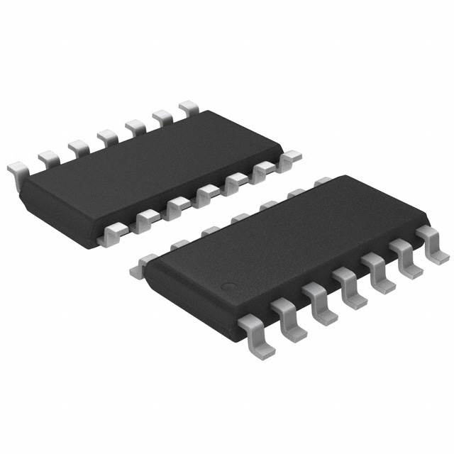
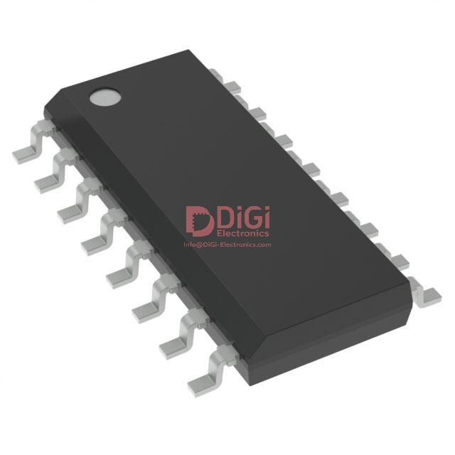
The VIPER16LD, from STMicroelectronics, is encapsulated in the SO16 narrow package, engineered for both high-voltage performance and manufacturing robustness. The structural integrity of the package is underpinned by carefully defined body and lead dimensions, optimizing layout compatibility while ensuring mechanical stress is distributed evenly during mounting and soldering. The package adheres to ECOPACK® environmental compliance, reflecting advanced material selection strategies—lead-free finishes and halogen-free molding compounds mitigate ecological impact and streamline process compatibility with RoHS and green assembly flows.
Creepage and clearance specifications are stringently maintained within the narrow SO16 outline to address high-voltage isolation, a critical requirement for offline switch-mode applications. These metrics are not just theoretical compliance values; in practice, maintaining adequate creepage along the molded surface becomes vital in high-density power supplies where PCB real estate is at a premium. Design experience demonstrates that the SO16 package layout, when paired with diligent PCB slotting or silkscreen controls, robustly mitigates risk of electrical arcing or surface tracking—frequently observed failure modes in high-voltage SMPS.
Dimensional precision is reflected in the controlled lead coplanarity and shape, enhancing automated optical inspection (AOI) visibility and reducing solder joint variability during reflow. This consistency is essential within high-throughput, automated SMT lines. Pin pitch uniformity contributes directly to assembly yield, as misalignment or skew during pick-and-place introduces latent mechanical or electrical failure potential—pain points routinely addressed with tight mechanical tolerances.
Application-specific demands, such as secure secondary-side isolation in charger designs or compliance with reinforced insulation requirements in metering and industrial power front ends, frequently exploit the VIPER16LD’s package geometry. Here, the balance between compactness and isolation is realized through both the internal lead frame architecture and external pinout arrangement, underscoring how mechanical design drives system-level safety and certification success.
A key insight, often observed during PCB prototyping and test, is the importance of matching package mechanical capability with thermal cycling resilience, especially in environments with intermittent load profiles. The SO16 narrow’s consistency in solderability and minimal warping under IR reflow strengthens joint reliability, minimizing open connections—a critical consideration in long-life or maintenance-averse applications. The integration of ECOPACK® principles not only addresses regulatory needs but simplifies global assembly logistics, reducing sourcing constraints and enabling streamlined qualification across multiple markets and end-use environments.
Taken as a whole, the mechanical packaging of the VIPER16LD enables a synergy between electrical safety, manufacturability, environmental responsibility, and operational reliability, making it a preferred choice in demanding offline switching applications.
Potential equivalent/replacement models for VIPER16LD STMicroelectronics IC OFFLINE SWITCH MULT TOP 16SO
In applications requiring flyback or buck converter topologies, the VIPER16LD IC from STMicroelectronics stands out due to its integration of a high-voltage, avalanche-rated power MOSFET and a robust PWM controller with advanced EMI reduction techniques. When evaluating equivalent or replacement options, it is crucial to dissect the device's integral functions and interface requirements, focusing first on the embedded 800V power MOSFET. Replacement candidates must demonstrate an equal or superior avalanche energy tolerance, ensuring protection against repetitive over-voltage events common in universal AC mains designs. Devices that fall short in this regard may introduce long-term reliability concerns or complicate compliance with safety standards.
The PWM controller segment warrants equally stringent analysis. Frequency jittering is engineered specifically to mitigate conducted and radiated EMI, an increasingly non-negotiable specification in modern consumer and industrial switch-mode power supplies. Prospective alternatives must incorporate either identical spread-spectrum techniques or demonstrate equivalent EMI performance through comparable modulation schemes. Controllers without this feature may necessitate external filtering, complicating PCB layout and BoM cost.
Current limitation and protection stratification are central for applications such as offline adapters, LED drivers, and compact SMPS modules. The integrated, adjustable current-limit mechanisms act as primary defenses against overstress events, while comprehensive built-in protections—such as thermal shutdown, overload, and open-loop safeguards—ensure fault-tolerant operation under real-world transient conditions. Replacement devices lacking these features often demand additional circuitry, offsetting the benefits of integration.
Package compatibility, while sometimes treated as a secondary attribute, plays a substantive role in deployment risk mitigation and time-to-market. The SO16 SMD footprint is widely adopted, easing drop-in replacements. Attention must be paid, however, to variations in thermal pad arrangements or pinouts among high-voltage switcher ICs. Even minor disparities may necessitate PCB redesigns or compromise heat dissipation, particularly in dense assemblies or power-dense applications.
Among in-family alternatives, the VIPER16LN remains attractive as it maintains almost identical silicon, diverging mostly in lead arrangements or specific mechanical envelope. Variants like the VIPER16HN/HD address higher switching frequency demands (115kHz), optimizing for reduced transformer size or specific EMI mask compliance. However, altered operating frequencies can impact core losses, output ripple, and component sizing, so cross-referencing application constraints becomes indispensable.
In field deployments, the most seamless replacements arise when verification protocols explicitly check thermal metrics, maximum device ratings, and dynamic response under fault induction and load transients. Merely matching datasheet “headline specs” has proven insufficient, as nuanced differences—like controller wakeup behavior, blanking times, or latch-off conditions—can manifest as erratic system-level performance. Custom validation on production-representative boards helps uncover these hidden interactions early.
An often underemphasized dimension involves the sourcing landscape—long-term supply chain risk for key power devices. Well-supported second sources, including series-compatible models from STMicroelectronics or equivalents from ON Semiconductor (e.g., their NCPxxx series) and Power Integrations (such as the TinySwitch family), offer stability, but each brings subtle differences in startup performance, line regulation, or transformer reset handling. Intelligent selection weighs not only electrical congruence but also the depth of application notes, reference designs, and field-proven reliability data.
Ultimately, effective VIPER16LD replacement hinges on a layered compatibility analysis, progressing from core electrical parameters to board-level deployment and long-term ecosystem support. Comprehensive evaluation safeguards project timelines while preserving the tightly integrated advantages that make this class of IC indispensable for compact AC-DC converters.
Conclusion
The VIPER16LD from STMicroelectronics stands out as a tightly integrated offline switch-mode power supply controller tailored for environments that demand both resilience and precision. At its core, the device leverages a high-voltage start-up cell combined with a rugged avalanche-rated MOSFET, enabling direct connection to rectified mains without additional external components. This integration streamlines board layout, minimizes bill of materials, and yields advantages in both form factor and electromagnetic compatibility.
The device’s topology flexibility extends across flyback, buck, and buck-boost configurations, allowing engineers to address a spectrum of output power and voltage requirements with minimal circuit redesign. This flexibility is particularly valuable in platform-based development cycles, where rapid customization or variant scaling is often necessary. The integrated current-mode control architecture underpins precise regulation and fast transient response, critical parameters for both energy efficiency mandates and system-level compliance with standards like IEC 62368-1.
A key aspect of the VIPER16LD’s robustness is its comprehensive suite of protection mechanisms, implemented in hardware to ensure real-time response. Features such as over-load, short-circuit, over-temperature, and over-voltage protection guard both converter integrity and downstream circuitry against abnormal events. The absence of external sensing solutions for these protections not only cuts system cost but also mitigates long-term reliability concerns associated with discrete implementation. In field deployments, this native protection circuitry translates into reduced return rates and lower total cost of ownership.
Design realization with the VIPER16LD benefits significantly from adherence to best practices in PCB layout—particularly in managing high di/dt loops, minimizing EMI emissions, and observing strict separation of high and low voltage domains. Practical design experience highlights the impact of proper grounding, optimal placement of snubbers, and critical component routing on converter stability and regulatory performance. These layout considerations become even more pivotal in compact or multi-output designs, where creepage, clearance, and thermal management have direct implications for product certification.
A recurring challenge in modern supply chains involves ensuring continuity when direct replacements or equivalent components are required. The VIPER16LD’s widespread industry acceptance, coupled with strong multi-source documentation, eases this concern. Comparative evaluation against alternative solutions underscores its advantage in integration and protection level, especially when the target application values extended lifecycle and uncompromised operation under voltage surges and thermal stress.
In diverse applications ranging from industrial auxiliary supplies to consumer electronics adapters, the controller’s efficiency over wide load conditions and tight protection algorithms deliver noticeably stable outputs. This characteristic supports seamless tuning and certification processes, especially in designs where regulatory margins are slim. The practical synergy of internal protection, topology versatility, and streamlined layout ultimately defines the VIPER16LD as a convergent choice for robust, forward-looking offline power supply architectures.