 >
>


Product overview: VIPER53DIP-E series converter
The VIPER53DIP-E series embodies a robust flyback topology integration, engineered to streamline offline switch-mode power supply development within demanding voltage contexts. At its foundation, the IC merges high-voltage startup circuitry, primary-side PWM control, and power MOSFET functionality, establishing a tightly-coupled architecture that minimizes external component count while optimizing thermal and EMI characteristics. This consolidation directly alleviates board complexity and supports aggressive miniaturization without compromising system stability under sustained load conditions.
Operational dynamics leverage internal frequency modulation, enabling switching rates up to 300kHz. This frequency domain flexibility promotes the use of smaller magnetics and filter components, driving higher power density and facilitating compact enclosure designs even at power levels approaching 50W in European line situations (195–265Vac) or 30W under universal input (85–265Vac). The ability to operate at elevated frequencies is complemented by adaptive zero-voltage switching techniques embedded in the core control logic. These mechanisms suppress switching losses and mitigate transient stress on both primary and secondary windings, which directly benefits the lifetime performance of the supply and downstream loads, especially in mission-critical industrial edge nodes.
Engineered for reliability, the VIPER53DIP-E series incorporates a suite of protection features including cycle-by-cycle current limiting, over-voltage protection via direct feedback sensing, and thermal shutdown. The result is a platform capable of withstanding repeated input voltage excursions and short-circuit events, without erratic behavior or over-stress to magnetic components. Field-deployment experiences reveal that this degree of integrated safeguarding helps maintain stable output regulation under fluctuating supply grids—a key requirement in automation panels and consumer appliances exposed to unpredictable brownouts.
Design implementations utilizing this family often benefit from straightforward transformer winding specifications due to primary-side regulation, thereby simplifying the design process for isolated power rails. The DIP package format is conducive to rapid prototyping and low-volume production, enabling efficient layout adjustments and facilitating compliance with insulation and clearance standards. Thermal dissipation in dense layouts is further eased by judicious MOSFET sizing embedded in the IC, minimizing the need for external heat sinks even in high-duty cycle use.
Subtle system-level advantages emerge when the VIPER53DIP-E is deployed in multi-output architectures; its frequency agility and soft-start operation significantly reduce cross-regulation challenges. High-frequency operation also advances transient response, which is particularly advantageous in digitally controlled auxiliary supplies or battery charging platforms requiring precise voltage tracking and stringent ripple suppression.
A core insight emerges from iterative deployment: in applications where rapid prototyping and high reliability intersect—such as smart meters, IoT gateways, and industrial ID markers—the VIPER53DIP-E series presents a compelling value proposition. The convergence of integrated safety protocols, broad input tolerance, and high switching efficiency addresses both regulatory and operational requirements. The architecture’s layered protection and optimized switch timing not only underpin robust converter design but set the stage for future scalability in systems where board space and compliance timelines are at a premium.
Device architecture and operating principle of VIPER53DIP-E
The VIPER53DIP-E exemplifies a compact, integrated power conversion solution engineered around the synergistic pairing of an advanced current-mode PWM controller and a high-voltage MDMesh Power MOSFET. This hybrid architecture natively supports primary-side regulation, which eliminates the need for optocouplers or elaborate secondary feedback paths, thereby streamlining both hardware complexity and control loop dynamics. The ability to directly sense output on the primary side significantly expedites design cycles and reduces bill-of-materials overhead, which is paramount in tightly constrained embedded systems and power adapters.
Fundamental operation centers on the flyback topology, deployed here for its intrinsic capacity to support both isolated and non-isolated output configurations. By integrating a robust high-voltage startup circuit, the device can interface directly with the AC mains, bypassing the requirement for auxiliary startup windings. This design attribute enables substantial footprint reduction and enhances overall reliability, particularly in environments subject to frequent transitional events such as brownouts or fluctuating grid conditions. The MDMesh MOSFET’s low Rds(on) and fast switching characteristics directly translate to elevated converter efficiency, reduced thermal dissipation, and relaxed requirements for heatsink sizing.
Frequency management is implemented via an external RC network, granting granular control over switching frequency up to 300 kHz. This flexibility is instrumental for designers pursuing targeted optimizations in electromagnetic interference, transformer design, and efficiency. For instance, adjusting the frequency upward facilitates transformer miniaturization at the expense of EMI, while lower frequencies can significantly mitigate conducted emissions and improve system robustness in EMC-critical deployments. Practical experience reveals that stability in the feedback loop under varying load conditions is preserved owing to the controller’s frequency-compensated current mode design, reducing audible noise and improving dynamic response without resorting to complex compensation networks.
An implicit advantage of the VIPER53DIP-E lies in its adaptability: the same core hardware can accommodate a broad spectrum of application scenarios, ranging from auxiliary power supplies in industrial automation to charger designs for consumer electronics and appliances. Over time, iterative deployment demonstrates resilience to component tolerances, with the architecture absorbing minor variations in passive elements without notable degradation in regulation accuracy or startup consistency.
A distinguishing insight emerges from the architectural cohesion of control and power stages. By co-locating high-voltage MOSFET and controller functions on the same silicon, the propagation delay is minimized, enhancing turn-on and turn-off timing precision. Consequently, designers gain additional latitude in transformer selection and winding strategy, directly impacting cost optimization and layout flexibility. In sum, the VIPER53DIP-E encapsulates a synthesis of topology, integration, and configurability that advances the operational ceiling for modern power conversion applications, elevating both design simplicity and performance reliability.
Key features and protections in VIPER53DIP-E converter
The VIPER53DIP-E converter incorporates distinct control and protection mechanisms designed to optimize efficiency, safety, and regulatory adherence. At its core, the adjustable current-mode control architecture combines finely tuned current limitation with dynamic response capabilities. This allows for rapid correction of output anomalies while preventing overstress on power components. The integration of precise current sensing ensures predictable behavior, particularly during load transients, providing engineers with a reliable platform for demanding applications.
Soft start and controlled shutdown routines are implemented via sequenced ramping of internal references and output signals. This mitigates both inrush current and voltage overshoot, critical for downstream component endurance and compliance with EMI restrictions. The converter also autonomously transitions to burst mode under decreased load conditions. This function minimizes switching losses and dramatically reduces standby power draw—qualifying designs for stringent low-power certifications. The burst mode implementation is responsive, exiting low-power states instantaneously upon detection of increased load, thus eliminating latency in resuming full operation.
A multi-layered fault protection scheme is embedded within the controller logic, enhancing operational integrity. Current limiting is actively enforced through real-time feedback monitoring, ensuring power handling remains within device limits regardless of external faults. Overload and short circuit events trigger timed resets, offering self-recovery features that reduce the need for manual intervention and increase system uptime. Overtemperature safeguards are realized using die-level thermal sensing, modulating converter operation before thermal runaway can occur. Undervoltage lockout mechanisms guarantee that system startup and shutdown are managed only under safe supply conditions, mitigating risks associated with unstable input sources.
The primary regulation loop utilizes a high-gain error amplifier, establishing tight control over output voltage against fluctuations and disturbances. This amplifier’s bandwidth and gain parameters are selected to maintain fast regulation without risking instability or excessive output ripple. A notable design insight is the amplifier’s resilience to secondary-side feedback failures—should feedback paths degrade or disconnect, primary-side regulation persists, offering a layer of fault tolerance indispensable for mission-critical and high-reliability environments.
These features translate into operational advantages across consumer, industrial, and environmental application scenarios. Field deployment has demonstrated that systems built with the VIPER53DIP-E maintain stable outputs under variable loads, with embedded protections consistently limiting downtime to rare, isolated events. Close monitoring of device performance shows that the combination of fast protection and adaptive control yields enhanced longevity, reduced maintenance, and simplified compliance with global eco-label regulations.
The architecture reflects a strategic balance between protection, efficiency, and adaptability. Deliberate choice of regulation topology and fault-handling logic ensures that both routine operation and exceptional fault events are managed seamlessly, positioning the VIPER53DIP-E as a foundation for high-density, high-reliability power systems where absolute control and robustness are mandatory.
Electrical characteristics of VIPER53DIP-E series
The electrical profile of the VIPER53DIP-E series addresses key design requirements for switch-mode power supplies in compact industrial and consumer platforms. Central to its architecture is a high-voltage, integrated MOSFET rated at 620V drain-source breakdown, exceeding standard input surges in most regional grids and supporting robust topology choices, including flyback and buck-boost designs. The device’s RDS(on) values—0.9Ω at 25°C, rising to 1.7Ω at 100°C—reflect a temperature-dependent loss profile that must be considered when sizing thermal management solutions; experience indicates that careful PCB layout and heat sinking play a pivotal role, particularly in dense assemblies where peak efficiency is expected under sustained high-load operation.
Peak drain current capability of 2A allows for dynamic load-handling under transient conditions, while the integrated blanking intervals and optimized sense delays efficiently mitigate spurious switchings originating from electromagnetic interference or fast transients. These temporal windows have been observed to enhance ruggedness against clamp voltage overshoots and help discriminate genuine fault events, streamlining protections at board level. The oscillator’s frequency flexibility—adjustable up to 300kHz with ±5% typical tolerance—opens the door to tailoring switching speeds for specific filtering and efficiency needs; designer insight suggests that operation at mid-to-high frequencies can significantly reduce transformer size, though careful EMC evaluation is essential.
The error amplifier combines a 45dB voltage gain with a 700kHz bandwidth, enabling tight loop control even in wide-output range applications. Such performance supports sophisticated feedback networks, particularly where ripple and cross-regulation are critical metrics. Extended experience with precision regulation circuits highlights how the amplifier’s fast transient response can suppress overshoots that otherwise affect downstream voltage rails, promoting overall system stability in digitally sensitive environments.
Supply voltage supervision is provisioned with both undervoltage and overvoltage thresholds, coupled with engineered hysteresis bands to avoid chattering or false trip-off events during noisy line conditions. This deliberate margining fortifies resilience throughout voltage sags and surges, with practical builds demonstrating that such integrated features significantly reduce reliance on external supervisory ICs—leading to lower BOM costs and simplified qualification. Underlying these characteristics is a holistic approach to integration, where every electrical parameter interlocks to support fail-safe design.
Balancing the device’s capabilities demands attention not only to absolute maximum ratings, but also to the interplay between switching frequency, power handling, and thermal strategy. When deploying the VIPER53DIP-E in field scenarios, leveraging the blanking/sensing timing, oscillator tuning, and feedback loop bandwidth has proven invaluable for optimizing reliability and performance in next-generation embedded systems.
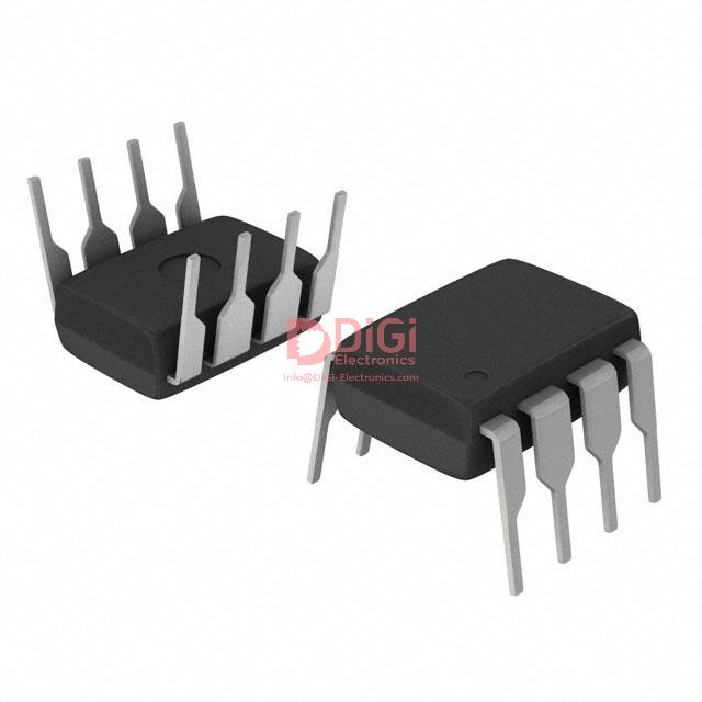
Pin configuration and functional roles in VIPER53DIP-E
Pin configuration in the VIPER53DIP-E 8-DIP package is engineered for efficient integration into power management architectures. Each pin serves a clearly delineated role within the control and switching ecosystem. The VDD pin supplies the internal control circuitry and incorporates precision voltage thresholds governing startup, shutdown, regulation stability, and overvoltage protection. This granular voltage management allows direct mapping of supply states to operational safety and control logic, minimizing the likelihood of fault-induced failures during transient or abnormal conditions.
SOURCE and DRAIN form the primary and secondary paths for power switching. The SOURCE pin anchors the switching element’s return, while DRAIN manages the output coupling to the transformer or load. Their positioning supports both topology flexibility—such as flyback or buck converters—and high-frequency switching integrity with minimized parasitic losses. Experience indicates that appropriate PCB layout attention to these pins, such as shortened high-current traces and minimized loop areas, significantly mitigates EMI and thermal drift.
The COMP pin is designed as a modulation network junction, directly influencing the feedback loop and system response. By integrating external resistors and capacitors, designers can fine-tune the control bandwidth, dynamic response, and set overload protection thresholds. This decoupling of compensation from the IC core supports application-specific optimization, and in practice, iterative tuning based on load transients and efficiency targets consistently yields improved regulation and robustness.
TOVL enables time-based overload management through an external capacitor. Its function offers precise control over delay timing under overload scenarios, essential for balancing fault protection and noise immunity. Capacitance selection here is critical—values too small may trigger premature shutdown, while excessive delay can compromise component safety. Empirical calibration based on stress testing across input line variations provides the most reliable overload response profile.
The OSC pin establishes system operating frequency via connection to an external RC network. This flexibility facilitates adaptation to desired switching speeds, which impacts both transformer design and EMI performance. Fine adjustments in the RC values can systematically reduce spurious emissions and optimize power conversion efficiency, especially in multi-output designs where cross-regulation is sensitive to operating frequency.
This pin architecture enables seamless application in both primary-side regulation—for isolated topologies without auxiliary windings—and secondary-side schemes, which leverage optocoupler feedback for precision voltage control. The modular nature of these functional assignments supports scalable power supply designs ranging from compact chargers to industrial-grade isolated converters. Layered understanding of these mechanisms—starting from individual pin functions to their integrated system behaviors—reveals that robust performance and flexible tuning are achieved when layout discipline, component value selection, and feedback calibration are tightly coupled within the design workflow.
Within advanced engineering practice, leveraging these pins not only simplifies functional integration but also elevates long-term reliability and adaptability in evolving regulatory environments. Systems benefit further from systematic pinout structuring, which underscores the importance of design modularity and resilience in contemporary power conversion solutions.
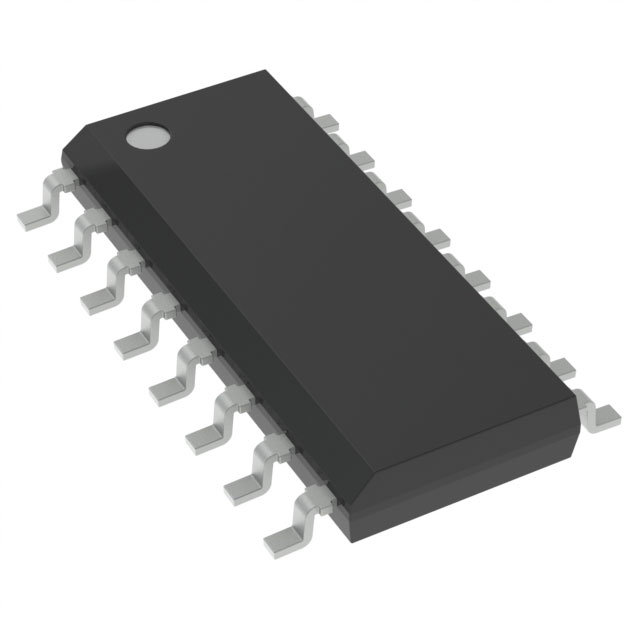
Thermal management for VIPER53DIP-E packages
Thermal management strategies for VIPER53DIP-E devices must account for their package-specific thermal characteristics and operating contexts. The VIPER53DIP-E comes in both DIP-8 and PowerSO-10 configurations, each presenting distinct paths for heat flow and dissipation efficiency. The DIP-8 package, with a junction-to-case thermal resistance (RθJC) of 20°C/W and junction-to-ambient (RθJA) of 80°C/W, demonstrates the importance of board layout and copper area in effective heat spreading. These figures assume standard mounting on a typical FR4 PCB with sufficient copper under and around the pads— deviations from this norm, such as minimal copper or double-sided mounting, can significantly impair heat transfer, elevating junction temperatures under sustained load.
The junction temperature range, specified from -40°C up to 150°C, defines reliable operational boundaries. On-chip thermal shutdown, activating typically between 140°C and 160°C, introduces an intrinsic failsafe against thermal overrun. Automatic recovery, enabled by hysteresis in the thermal protection circuit, prevents oscillatory fault behavior and ensures system integrity during fault clearance or intermittent overloads. However, dependence solely on the device’s shutdown may be insufficient in high-reliability or space-constrained systems, where proactive measures—such as optimized copper heatsinking, external heat spreaders, or controlled airflow—are advisable.
PCB real estate and copper optimization stand out among passive strategies. Expanding copper planes beneath the device, connecting thermal vias to inner or opposite layer copper, and integrating thermal reliefs at pad interfaces all decrease effective RθJA. Empirical evaluation can clarify the impact: measuring actual case and ambient temperatures under maximum load, then back-calculating RθJA, often reveals divergence from datasheet benchmarks—pinpointing the effect of specific board geometries or environmental constraints such as enclosure airflow.
Component orientation and proximity to heat sources demand judicious attention. Mounting devices vertically to exploit natural convection, or spacing high-dissipation parts to mitigate localized hotspots, contributes to uniform board thermal profile. In scenarios where passive dissipation proves inadequate, localized airflow or small-form fans may offer incremental headroom, especially in dense assemblies.
Thermal integrity of VIPER53DIP-E also affects circuit reliability and operational lifespan; repeated exposure to temperatures near shutdown reduces component longevity and may alter parametric behavior. Conservative thermal design not only prevents tripping protection thresholds but also aligns with predictive maintenance goals in industrial or mission-critical deployments. Subtle variations in soldering quality or board finish can influence heat conduction, underlining the value of process control and thorough post-assembly inspection.
System architects benefit from integrating early thermal simulation during board design, correlating simulated hot-spot maps with prototype thermography. This approach informs decisions on trace width, copper weight, and routing—key parameters in compact power supplies where every degree of margin is valuable. Continuous monitoring using built-in temperature indicators or external sensors further refines operational predictability.
In summary, leveraging DIP-8 and PowerSO-10 packages to their fullest potential necessitates a layered approach to thermal management: quantitative characterization, board-level design for enhanced dissipation, empirical validation, and ongoing system optimization. These measures enable cost-effective and high-reliability deployment of VIPER53DIP-E in both compact and power-dense applications, anchored by engineering practices that anticipate and mitigate thermal risks before they can impact functionality.
Application scenarios and engineering guidelines for VIPER53DIP-E
VIPER53DIP-E drives significant advancements in the design of offline switch-mode power supplies, specifically within applications demanding high efficiency, robust safety compliance, and compact PCB footprints. Its architecture, centered on a current-mode PWM controller integrated with a rugged 800V avalanche-rugged power MOSFET, natively accommodates wide input voltage ranges, enabling stable operation in both universal mains and lower-voltage industrial environments. The core current-mode control loop ensures intrinsic cycle-by-cycle current limitation and precise output regulation, fostering fast transient responses critical for peripherals in consumer and industrial domains—such as set-top boxes, HVAC controllers, and metering equipment—where load variations occur frequently.
The VIPER53DIP-E’s comprehensive suite of protections, including thermal shutdown, overload mapping via external capacitor (TOVL pin), and dual-level overcurrent protection, forms a foundation for reliable field operation. These features mitigate risks from user error, component aging, or unpredictable input surges, translating into reduced warranty costs and increased long-term product viability. A nuanced approach to RC network selection on the oscillator (OSC) pin is essential—not only for programming switching frequency to suit EMI constraints and efficiency targets, but also for avoiding subharmonic oscillations or frequency jitter, which can compromise both conducted and radiated emission profiles.
Particular care must be afforded to PCB layout. Locating high di/dt paths close to the device, ensuring tight grounding around the source and controller, and segregating sensitive signal traces minimize crosstalk and EMI. For thermal performance, optimal copper area under the device and a well-designed heat-spreading strategy ensure MOSFET junction temperature remains comfortably below threshold values under both steady-state and overload conditions, enabling the full utilization of its power handling capability in convection-cooled applications.
VIPER53DIP-E’s error amplifier and flexible feedback topology provide a clear pathway for both primary-side and secondary-side regulation schemes. In simpler applications, leveraging the internal error amplifier ensures straightforward integration with voltage-divider feedback networks. In more demanding designs, its compatibility with optocoupler-isolated feedback allows architects to easily meet stringent cross-regulation and load transient targets found in multi-output or intelligent auxiliary platforms. Notably, this flexibility de-risks migration from earlier discrete implementations or when upgrading topology for improved efficiency and part count reduction; the pinout and functional symmetry of the feedback block promote rapid protyping and streamlined validation cycles.
Experience shows that leveraging the adjustable overload delay, configured via external capacitor on the TOVL pin, guards against nuisance shutdown during inrush or start-up events typical when driving capacitive loads or motors. Proper capacitance sizing here is often underestimated but proves crucial in ensuring robust system start-up in field deployments characterized by variable or harsh line conditions.
A critical insight is that VIPER53DIP-E's feature integration does not constrain but rather enables creative adaptation to both legacy and emerging design challenges. Its high level of functional density, when exploited through disciplined application of classic engineering guidelines—thorough network selection, power path optimization, and feedback loop tailoring—consistently translates into reduced design iterations, shorter time-to-certification, and enhanced product differentiation, especially in space- and regulation-constrained market segments.
Potential equivalent/replacement models for VIPER53DIP-E
Identifying functional equivalents or superior replacements for the VIPER53DIP-E requires a granular understanding of topology and performance trade-offs in integrated off-line flyback controllers. The VIPer53-E family itself, especially versions in PowerSO-10 packaging, extends the core features of the DIP variant by increasing power dissipation ceilings and enhancing thermal conductivity—an essential consideration for densely-packed or passively cooled designs. Thermal management intricacies are often underestimated during package selection; leveraging PowerSO-10 enables more generous derating, which is a decisive margin in high-ambient or compact layouts.
Migration within the broader VIPERTM series introduces additional flexibility in tailoring input voltage headroom, output current, and protection schemes. Emerging VIPER solutions, for instance, offer higher peak current limits and expanded Vcc UVLO thresholds, facilitating adoption in either universal or regional mains environments. These newer iterations also frequently integrate advanced soft-start, overload, and input brown-in/brown-out detection circuitry, which streamline certification efforts in safety-conscious applications—such as white goods or metering systems—where regulatory margins are narrow and transient robustness is mandatory.
When assessing alternatives across vendors or within the STMicroelectronics portfolio, a disciplined approach involves not only ensuring pin compatibility and electrical congruence but also matching dynamic switching profiles. Oscillator tolerances, propagation delays, and soft-shutdown behaviors influence EMI emissions and turnkey qualification. Reference designs built around VIPER53, VIPER35, and their peers—sometimes incorporating variants with integrated primary-side regulation—often demonstrate application-level nuances such as transformer selection, feedback loop compensation, and layout practices that can significantly expedite debug cycles and reduce time-to-certification.
Key decision criteria extend well beyond datasheet cross-comparison. Input voltage range must comfortably encompass local supply aberrations and brownout conditions. Switching frequency stability, considering both EMI optimization and transformer core material, is non-negotiable for stringent efficiency and conducted emission targets. Fault protection depth—covering short-circuit, overload, over-temperature and open-loop scenarios—directly impacts system MTBF and customer satisfaction rates in field deployments. Crucially, package junction-to-ambient thermal resistance must be validated against realistic PCB stackups, airflow conditions, and assembly constraints rather than nominal test fixtures.
Practical design cycles often underline the value of pre-verified application notes and evaluation boards to stress-test functional and thermal boundaries of replacement candidates. Direct substitutions occasionally necessitate iterative adjustments in snubber values, transformer leakage inductance, or PCB copper pour for heat spreading. Subtle variations in fault response or startup current profiles can reveal board-level dependencies not visible in isolated bench tests. In multi-sourced workflows, maintaining consistent board footprints and debug interfaces streamlines future flexibility and supply chain risk mitigation.
Ultimately, robust equivalence evaluation demands a holistic perspective, balancing electrical, mechanical, regulatory, and lifecycle considerations. This systems-minded approach yields architectures that not only drop into legacy sockets but also raise headroom for future enhancements, reliability margins, and compliance confidence in evolving end markets.
Conclusion
VIPER53DIP-E from STMicroelectronics exemplifies a consolidated flyback controller design optimized for efficient offline power conversion across diverse voltage and power specifications. At its core, the device implements precise pulse-width modulation (PWM), underpinning the stable regulation of output voltage and current while minimizing switching losses—an essential consideration in high-efficiency applications. The integration of a full protection suite, including overvoltage, overload, and thermal shutdown functionalities, forms a resilient safety layer, enabling consistent operation even in challenging environments with variable input conditions or load surges.
The flexible pin configuration supports streamlined PCB layouts and accommodates a variety of topologies, facilitating compact product integrations without compromising electrical integrity. This adaptability extends to package options, allowing ease of thermal management and mechanical fit in both low-profile consumer designs and industrial power modules. Explicit electrical and thermal parameters provided by the manufacturer simplify the design phase, fostering predictive simulation and accurate worst-case calculations in development workflows.
From a practical standpoint, deploying the VIPER53DIP-E yields distinct advantages in EMI performance and fault recovery, reducing system-level design iterations. The device's internal start-up circuitry further enhances reliability by eliminating external components and mitigating potential failure points associated with discrete implementations. Experience shows that this architecture accelerates time-to-market for new product releases, especially where efficiency and form-factor constraints dictate topology selection.
A critical viewpoint emerges when considering the strategic balance between integration and flexibility. By embedding advanced features while retaining versatility in external component selection, the VIPER53DIP-E provides a scalable solution that supports both rapid prototyping and robust production deployment. The presence of carefully documented equivalent models also streamlines cross-referencing in supply chains, ensuring continuity amid fluctuating part availability—a recurring challenge in modern electronics engineering.
Converging these aspects reinforces VIPER53DIP-E's position as a reference point for offline converter IC selection. Its layered protection mechanisms, fine-tuned control algorithms, and practical implementation benefits accommodate both the stringent demands of industrial standards and the nuanced challenges of commercial consumer electronics. This multi-dimensional engineering approach, embedded within the device architecture and support ecosystem, enables seamless adaptation to evolving application requirements and fosters confidence in long-term reliability and system optimization.