


Request Quote
(Ships tomorrow)
VN10LPSTZ N-Channel MOSFET Equivalent & Substitute Parts
Part Overview
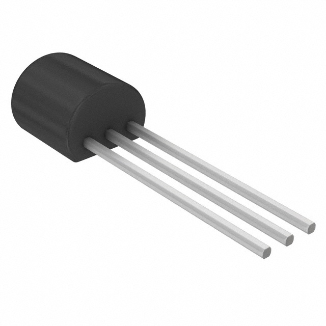
The VN10LPSTZ is an N-Channel MOSFET manufactured by Diodes Incorporated, designed for through-hole applications in the TO-92 compatible E-Line package. This device operates at 60 V drain-to-source voltage with a continuous drain current rating of 270 mA at 25°C and maximum power dissipation of 625 mW. The part is Active in product status and RoHS3 compliant. Substitute parts are identified based on matching electrical characteristics and mechanical compatibility within the N-Channel MOSFET category.
Substiute Parts
Key Parameters
| Parameter | Value | Unit |
|---|---|---|
| Drain to Source Voltage (Vdss) | 60 | V |
| Continuous Drain Current (Id) @ 25°C | 270 | mA |
| Power Dissipation (Max) | 625 | mW |
| Rds On (Max) @ 500mA, 10V | 5 | Ohm |
| Vgs(th) (Max) @ 1mA | 2.5 | V |
| Vgs (Max) | ±20 | V |
| Input Capacitance (Ciss) @ 25V | 60 | pF |
| Operating Temperature Range | -55 to 150 | °C |
| Mounting Type | Through Hole | |
| Package | E-Line-3, Formed Leads |
Substitute Part Grouping Explanation
Substitute parts for the VN10LPSTZ are identified based on the following critical parameters that determine functional equivalence:
Electrical Compatibility Criteria:
- Drain to Source Voltage (Vdss): 60 V minimum
- FET Type: N-Channel
- Technology: MOSFET (Metal Oxide)
- Gate-Source Voltage (Vgs): ±20 V maximum rating
- Operating Temperature Range: -55°C to 150°C
Mechanical Compatibility Criteria:
- Mounting Type: Through Hole
- Package Type: TO-92-3 compatible
Regulatory Compliance:
- RoHS3 Compliant
- REACH Unaffected
- ECCN: EAR99
The substitute parts 2N7000-D26Z, 2N7000-D74Z, and 2N7000-D75Z from onsemi meet these criteria. These devices share identical Vdss ratings, gate voltage specifications, and operating temperature ranges. While the substitute parts have lower continuous drain current ratings (200 mA versus 270 mA) and reduced power dissipation (400 mW versus 625 mW), they maintain electrical compatibility for applications within their specified current and power limits.
Parameter Comparison
| Parameter | VN10LPSTZ (Diodes) | 2N7000-D26Z (onsemi) | 2N7000-D74Z (onsemi) | 2N7000-D75Z (onsemi) | Unit |
|---|---|---|---|---|---|
| Drain to Source Voltage (Vdss) | 60 | 60 | 60 | 60 | V |
| Continuous Drain Current (Id) @ 25°C | 270 | 200 | 200 | 200 | mA |
| Power Dissipation (Max) | 625 | 400 | 400 | 400 | mW |
| Rds On (Max) @ 500mA, 10V | 5 | 5 | 5 | 5 | Ohm |
| Vgs(th) (Max) @ 1mA | 2.5 | 3 | 3 | 3 | V |
| Vgs (Max) | ±20 | ±20 | ±20 | ±20 | V |
| Input Capacitance (Ciss) @ 25V | 60 | 50 | 50 | 50 | pF |
| Operating Temperature Range | -55 to 150 | -55 to 150 | -55 to 150 | -55 to 150 | °C |
| Package Type | E-Line-3, Formed Leads | TO-226-3, TO-92-3 (TO-226AA) Formed Leads | TO-226-3, TO-92-3 (TO-226AA) Formed Leads | TO-226-3, TO-92-3 (TO-226AA) Formed Leads | |
| RoHS Status | ROHS3 Compliant | ROHS3 Compliant | ROHS3 Compliant | ROHS3 Compliant | |
| Product Status | Active | Active | Active | Active |
Engineering Selection Recommendations
All substitute parts listed are Active products with RoHS3 compliance and REACH unaffected status, matching the regulatory posture of the VN10LPSTZ. The 2N7000-D26Z, 2N7000-D74Z, and 2N7000-D75Z devices are functionally equivalent for applications requiring N-Channel MOSFET operation at 60 V with through-hole TO-92-3 package mounting.
Selection among the three substitute options should be based on application current requirements. The VN10LPSTZ supports 270 mA continuous drain current; substitute parts are rated for 200 mA continuous drain current. Applications operating below 200 mA at 25°C are compatible with all substitute parts. Applications requiring drain currents between 200 mA and 270 mA require the VN10LPSTZ.
The substitute parts exhibit slightly higher gate-source threshold voltage (3 V versus 2.5 V) and lower input capacitance (50 pF versus 60 pF), which may affect switching characteristics in gate-drive-sensitive applications. Drain-source on-resistance remains identical at 5 Ohm across all devices.
Frequently Asked Questions (FAQ)
Q: Can the 2N7000-D26Z, 2N7000-D74Z, or 2N7000-D75Z be used as direct replacements for the VN10LPSTZ?
A: These parts are electrically compatible for applications operating at or below 200 mA continuous drain current. The VN10LPSTZ supports higher current (270 mA) and power dissipation (625 mW). Direct substitution is valid only when application current requirements do not exceed the 200 mA rating of the substitute parts.
Q: Are the packages physically compatible?
A: The VN10LPSTZ uses an E-Line-3 package with formed leads, while substitute parts use TO-92-3 (TO-226AA) packages with formed leads. Both are through-hole configurations with three leads in similar physical arrangements. Pin-to-pin compatibility should be verified against specific PCB footprint requirements.
Q: What is the difference in gate-source threshold voltage between the VN10LPSTZ and substitute parts?
A: The VN10LPSTZ has a maximum Vgs(th) of 2.5 V at 1 mA, while substitute parts specify 3 V at 1 mA. This 0.5 V difference may affect gate drive timing and switching speed in circuits with marginal gate voltage margins.
Q: Do all parts meet the same regulatory requirements?
A: Yes. The VN10LPSTZ and all three substitute parts are RoHS3 compliant, REACH unaffected, and classified under ECCN EAR99. Regulatory compliance is equivalent across all options.
Q: What is the inventory status of substitute parts?
A: 2N7000-D26Z has 14,893 pieces in stock, 2N7000-D74Z has 3,200 pieces in stock, and 2N7000-D75Z has 8,771 pieces in stock. The VN10LPSTZ has 9,300 pieces in stock.
Q: How do the input capacitance values differ?
A: The VN10LPSTZ specifies 60 pF input capacitance at 25 V, while substitute parts specify 50 pF at 25 V. This 10 pF difference may affect high-frequency switching performance and gate charge characteristics.
Alternative Parts

SJ6012L2TP
Littelfuse Inc.
6 Alternative Parts

JMK107BBJ476MA-RE
Taiyo Yuden
10 Alternative Parts

GMK107BBJ475MA-T
Taiyo Yuden
5 Alternative Parts
SJ6020N2ARP
Littelfuse Inc.
3 Alternative Parts
SJ6025R2ATP
Littelfuse Inc.
4 Alternative Parts

2474-05L
API Delevan Inc.
1 Alternative Parts

4590R-684K
API Delevan Inc.
1 Alternative Parts

CM6560R-334
API Delevan Inc.
1 Alternative Parts

CM6460-104
API Delevan Inc.
1 Alternative Parts

5526-12
API Delevan Inc.
1 Alternative Parts