


Request Quote
(Ships tomorrow)
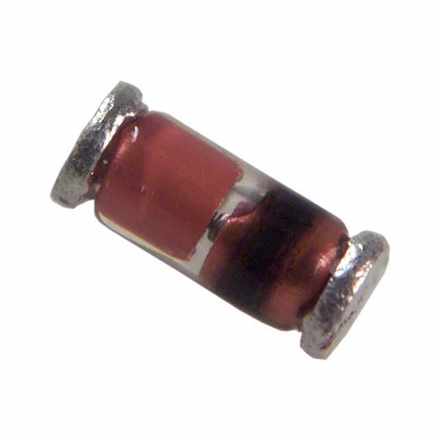
VLZ18B-GS18 Equivalent & Substitute Parts
Part Overview
The VLZ18B-GS18 is a Zener diode rated at 17.26 V nominal with 500 mW power dissipation in a SOD-80 QuadroMELF surface mount package. Manufactured by Vishay General Semiconductor - Diodes Division, this component is classified as Obsolete. Due to its obsolete status and limited availability for new designs, equivalent substitute parts are necessary to maintain circuit functionality while ensuring access to active product lines and improved supply chain reliability.
Substiute Parts
Key Parameters
| Parameter | Value |
|---|---|
| Voltage - Zener (Nom) (Vz) | 17.26 V |
| Power - Max | 500 mW |
| Impedance (Max) (Zzt) | 23 Ohms |
| Current - Reverse Leakage @ Vr | 40 µA @ 16 V |
| Voltage - Forward (Vf) (Max) @ If | 1.5 V @ 200 mA |
| Operating Temperature Range | -65°C ~ 175°C |
| Mounting Type | Surface Mount |
| Package / Case | SOD-80 QuadroMELF |
| Grade | Automotive |
| Qualification | AEC-Q101 |
| RoHS Status | ROHS3 Compliant |
Substitute Part Grouping Explanation
Substitution of the VLZ18B-GS18 is determined by the following critical parameters:
Electrical Compatibility Criteria:
- Zener voltage within acceptable circuit tolerance (nominal voltage range 17.26 V to 18 V)
- Power dissipation rating of 500 mW minimum
- Operating temperature range of -65°C to 175°C minimum
- Surface mount technology requirement
Mechanical Compatibility Criteria:
- SOD-80 package family (includes SOD-80 QuadroMELF and SOD-80 MiniMELF variants)
- Alternative surface mount packages (DO-213AA, DO-213AC) acceptable if electrical parameters align
Compliance Criteria:
- RoHS3 compliance preferred for new designs
- AEC-Q101 automotive qualification maintained where available
The substitute parts listed below satisfy these criteria with documented electrical and mechanical compatibility.
Parameter Comparison
| Parameter | VLZ18B-GS18 (Main) | TLZ18B-GS18 (Substitute) | 1N4112UR-1 (Substitute) |
|---|---|---|---|
| Manufacturer | Vishay General Semiconductor | Vishay General Semiconductor | Microchip Technology |
| Voltage - Zener (Nom) (Vz) | 17.26 V | 18 V | 18 V |
| Tolerance | - | - | ±5% |
| Power - Max | 500 mW | 500 mW | 500 mW |
| Impedance (Max) (Zzt) | 23 Ohms | 23 Ohms | 100 Ohms |
| Current - Reverse Leakage @ Vr | 40 µA @ 16 V | 40 nA @ 16 V | 50 nA @ 13.7 V |
| Voltage - Forward (Vf) (Max) @ If | 1.5 V @ 200 mA | 1.5 V @ 200 mA | 1.1 V @ 200 mA |
| Operating Temperature Range | -65°C ~ 175°C | -65°C ~ 175°C | -65°C ~ 175°C (TJ) |
| Mounting Type | Surface Mount | Surface Mount | Surface Mount |
| Package / Case | SOD-80 QuadroMELF | SOD-80 MiniMELF | DO-213AA |
| Product Status | Obsolete | Active | Active |
| RoHS Status | ROHS3 Compliant | ROHS3 Compliant | RoHS non-compliant |
| Grade | Automotive | Not specified | Not specified |
| Qualification | AEC-Q101 | Not specified | Not specified |
Engineering Selection Recommendations
TLZ18B-GS18 (Vishay General Semiconductor - Diodes Division):
This substitute is the primary equivalent for the VLZ18B-GS18. Both components are manufactured by Vishay and share identical electrical specifications: 500 mW power rating, 23 Ohms maximum impedance, and -65°C to 175°C operating temperature range. The TLZ18B-GS18 operates at 18 V nominal zener voltage compared to 17.26 V, representing a 0.74 V difference within typical circuit tolerance margins. The TLZ18B-GS18 is Active product status with ROHS3 compliance. The primary mechanical difference is the package variant: SOD-80 MiniMELF versus SOD-80 QuadroMELF. Both are SOD-80 family packages suitable for surface mount applications. Reverse leakage current is significantly improved at 40 nA versus 40 µA. This substitute is recommended for applications where Vishay continuity and RoHS3 compliance are required.
1N4112UR-1 (Microchip Technology):
This substitute provides functional equivalence with 18 V nominal zener voltage and 500 mW power rating. The component is Active product status with -65°C to 175°C operating temperature range. Key differences include: impedance of 100 Ohms (versus 23 Ohms), lower forward voltage of 1.1 V at 200 mA (versus 1.5 V), and RoHS non-compliance. The package is DO-213AA surface mount, compatible with SOD-80 family footprints. Reverse leakage current is 50 nA at 13.7 V, superior to the main part. This substitute is suitable for applications where RoHS compliance is not mandated and impedance variation is acceptable. The ±5% voltage tolerance provides explicit specification compared to the main part.
Frequently Asked Questions (FAQ)
Q: Can the TLZ18B-GS18 directly replace the VLZ18B-GS18 in existing designs?
A: The TLZ18B-GS18 provides electrical equivalence with 18 V nominal zener voltage versus 17.26 V. The 0.74 V difference must be evaluated against circuit tolerance requirements. Both components share identical power ratings (500 mW), impedance (23 Ohms), and operating temperature range (-65°C to 175°C). Package compatibility requires verification: TLZ18B-GS18 uses SOD-80 MiniMELF while VLZ18B-GS18 uses SOD-80 QuadroMELF. Both are SOD-80 family packages with surface mount compatibility.
Q: What is the significance of the impedance difference between TLZ18B-GS18 (23 Ohms) and 1N4112UR-1 (100 Ohms)?
A: Impedance affects dynamic zener regulation characteristics. The 1N4112UR-1 impedance of 100 Ohms is higher than both the main part and TLZ18B-GS18 at 23 Ohms. This impacts voltage regulation under load transients. Applications requiring tight voltage regulation should prioritize the TLZ18B-GS18 due to lower impedance matching the original specification.
Q: Is the 1N4112UR-1 suitable for automotive applications?
A: The 1N4112UR-1 is not specified with automotive grade or AEC-Q101 qualification. The VLZ18B-GS18 carries Automotive grade and AEC-Q101 qualification. For automotive applications, the TLZ18B-GS18 is the preferred substitute as it maintains Vishay manufacturing and active product status, though automotive qualification is not explicitly stated in available data.
Q: What is the impact of reverse leakage current differences?
A: The VLZ18B-GS18 specifies 40 µA reverse leakage at 16 V. Both substitutes show significantly lower leakage: TLZ18B-GS18 at 40 nA and 1N4112UR-1 at 50 nA. Lower reverse leakage improves circuit performance by reducing standby current and improving regulation stability. This represents an improvement over the original specification.
Q: Are there packaging considerations for PCB layout migration?
A: The VLZ18B-GS18 uses SOD-80 QuadroMELF package. The TLZ18B-GS18 uses SOD-80 MiniMELF package. Both are SOD-80 family with surface mount technology. The 1N4112UR-1 uses DO-213AA package. PCB footprint compatibility must be verified during design migration. SOD-80 variants may have different lead spacing and body dimensions requiring layout adjustment.
Q: Why is RoHS compliance status different between substitutes?
A: The TLZ18B-GS18 is ROHS3 compliant, matching the original VLZ18B-GS18. The 1N4112UR-1 is RoHS non-compliant. For applications subject to RoHS regulations or customer requirements, the TLZ18B-GS18 is the appropriate selection. RoHS compliance affects material composition and environmental regulatory acceptance.
Q: What is the voltage tolerance impact of the ±5% specification on 1N4112UR-1?
A: The 1N4112UR-1 specifies ±5% voltage tolerance on the 18 V nominal rating, resulting in a range of 17.1 V to 18.9 V. The VLZ18B-GS18 and TLZ18B-GS18 do not specify tolerance values. For applications requiring tighter voltage control, explicit tolerance specification on the 1N4112UR-1 provides measurable quality assurance, though the wider tolerance band must be evaluated against circuit requirements.
Alternative Parts

SJ6012L2TP
Littelfuse Inc.
6 Alternative Parts

JMK107BBJ476MA-RE
Taiyo Yuden
10 Alternative Parts

GMK107BBJ475MA-T
Taiyo Yuden
5 Alternative Parts
SJ6020N2ARP
Littelfuse Inc.
3 Alternative Parts
SJ6025R2ATP
Littelfuse Inc.
4 Alternative Parts

2474-05L
API Delevan Inc.
1 Alternative Parts

4590R-684K
API Delevan Inc.
1 Alternative Parts

CM6560R-334
API Delevan Inc.
1 Alternative Parts

CM6460-104
API Delevan Inc.
1 Alternative Parts

5526-12
API Delevan Inc.
1 Alternative Parts