


Request Quote
(Ships tomorrow)
VLS3015ET-470M Equivalent & Substitute Parts
Part Overview
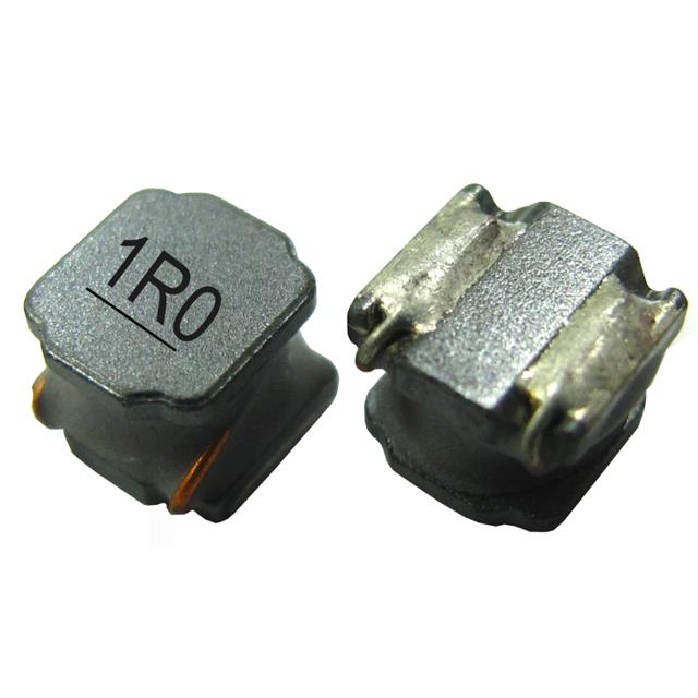
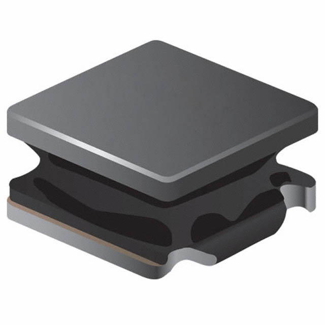
The VLS3015ET-470M is a 47 µH shielded drum core wirewound inductor manufactured by TDK Corporation, rated for 320 mA with a maximum DC resistance of 1.5 Ohm. This surface mount component is designed for applications requiring fixed inductance in compact form factors. The part is classified as "Not For New Designs," making identification of functionally equivalent alternatives necessary for ongoing production support and design flexibility.
Substiute Parts
Key Parameters
| Parameter | Value |
|---|---|
| Inductance | 47 µH |
| Current Rating | 320 mA |
| DC Resistance (DCR) | 1.5 Ohm Max |
| Inductance Tolerance | ±20% |
| Core Material | Ferrite |
| Shielding | Shielded |
| Operating Temperature Range | -40°C ~ 105°C |
| Mounting Type | Surface Mount |
| Package Size | 3.00mm x 3.00mm |
| Height (Seated Max) | 1.50mm |
| RoHS Status | ROHS3 Compliant |
Substitute Part Grouping Explanation
Substitution eligibility for the VLS3015ET-470M is determined by the following critical parameters:
- Inductance Value: Must be 47 µH with tolerance of ±20% or tighter
- Current Rating: Must support minimum 320 mA continuous operation
- DC Resistance: Must not exceed 1.5 Ohm to maintain circuit performance
- Core Material: Ferrite core required for electromagnetic characteristics
- Shielding: Shielded configuration required to minimize EMI coupling
- Package Footprint: 3.00mm x 3.00mm surface mount footprint
- Height Constraint: Maximum seated height of 1.50mm for PCB clearance
- Compliance: ROHS3 compliance required
Parts meeting all these criteria are classified as direct substitutes. Parts exceeding current rating or DCR specifications while maintaining other parameters are classified as upgraded alternatives suitable for higher-performance applications.
Parameter Comparison
| Part Number | Manufacturer | Inductance | Current Rating (mA) | DCR (Ohm Max) | Tolerance | Shielding | Height (mm) | Product Status |
|---|---|---|---|---|---|---|---|---|
| VLS3015ET-470M | TDK Corporation | 47 µH | 320 | 1.5 | ±20% | Shielded | 1.50 | Not For New Designs |
| VLS3012CX-470M-1 | TDK Corporation | 47 µH | 660 | 1.477 | ±20% | Shielded | 1.20 | Active |
| BWVF00303015470M00 | Pulse Electronics | 47 µH | 370 | 1.5 | ±20% | Shielded | 1.50 | Active |
| BWVF00303015470T00 | Pulse Electronics | 47 µH | 370 | 1.5 | ±30% | Shielded | 1.50 | Active |
| SRN3015-470M | Bourns Inc. | 47 µH | 400 | 1.406 | ±20% | Semi-Shielded | 1.50 | Active |
| TYS3012470M-10 | Laird-Signal Integrity Products | 47 µH | 350 | 1.885 | ±20% | Shielded | 1.40 | Active |
Engineering Selection Recommendations
Direct Substitutes (Fully Compatible)
BWVF00303015470M00 and BWVF00303015470T00 from Pulse Electronics meet all electrical and mechanical specifications of the VLS3015ET-470M. Both maintain 47 µH inductance, 1.5 Ohm DCR, shielded configuration, and identical 3.00mm x 3.00mm footprint with 1.50mm height. Both are ROHS3 compliant and active products. The BWVF00303015470M00 variant maintains ±20% tolerance matching the original specification, while BWVF00303015470T00 offers ±30% tolerance with lower inventory availability.
Upgraded Alternatives (Enhanced Performance)
VLS3012CX-470M-1 from TDK Corporation provides superior current handling at 660 mA with reduced height of 1.20mm, maintaining identical inductance and DCR specifications. This part is suitable for applications requiring higher current capacity within the same footprint.
SRN3015-470M from Bourns Inc. supports 400 mA current rating with DCR of 1.406 Ohm, both exceeding original specifications. However, this part features semi-shielded rather than fully shielded construction, which may affect EMI performance in sensitive applications.
TYS3012470M-10 from Laird-Signal Integrity Products supports 350 mA with DCR of 1.885 Ohm. The elevated DCR specification exceeds the original 1.5 Ohm maximum and requires circuit validation before implementation.
Frequently Asked Questions (FAQ)
Q: Can VLS3012CX-470M-1 be used as a direct replacement for VLS3015ET-470M?
A: Yes. VLS3012CX-470M-1 maintains identical inductance (47 µH), tolerance (±20%), and DCR (1.477 Ohm), all within specification. The reduced height (1.20mm vs 1.50mm) provides additional PCB clearance. Current rating of 660 mA exceeds the original 320 mA requirement.
Q: What is the difference between BWVF00303015470M00 and BWVF00303015470T00?
A: Both parts are electrically and mechanically identical with one exception: BWVF00303015470M00 maintains ±20% inductance tolerance matching the original specification, while BWVF00303015470T00 specifies ±30% tolerance. BWVF00303015470M00 is preferred for applications with tighter inductance requirements.
Q: Why is SRN3015-470M listed as an alternative if it uses semi-shielded construction?
A: SRN3015-470M meets all electrical parameters and maintains the 3.00mm x 3.00mm footprint. Semi-shielded construction provides reduced but not eliminated EMI isolation. Applications requiring full shielding should use fully shielded alternatives.
Q: Can TYS3012470M-10 be used in place of VLS3015ET-470M?
A: TYS3012470M-10 meets inductance and current requirements but specifies maximum DCR of 1.885 Ohm, exceeding the original 1.5 Ohm specification. Circuit validation is required to confirm acceptable performance with elevated resistance.
Q: Are all substitute parts ROHS3 compliant?
A: Yes. All listed substitute parts maintain ROHS3 compliance matching the original VLS3015ET-470M specification.
Q: What is the footprint compatibility of these parts?
A: All substitute parts maintain the 3.00mm x 3.00mm surface mount footprint. Height variations range from 1.20mm to 1.50mm seated maximum. PCB layout clearance must accommodate the specific height of the selected part.
Alternative Parts

SJ6012L2TP
Littelfuse Inc.
6 Alternative Parts

JMK107BBJ476MA-RE
Taiyo Yuden
10 Alternative Parts

GMK107BBJ475MA-T
Taiyo Yuden
5 Alternative Parts
SJ6020N2ARP
Littelfuse Inc.
3 Alternative Parts
SJ6025R2ATP
Littelfuse Inc.
4 Alternative Parts

2474-05L
API Delevan Inc.
1 Alternative Parts

4590R-684K
API Delevan Inc.
1 Alternative Parts

CM6560R-334
API Delevan Inc.
1 Alternative Parts

CM6460-104
API Delevan Inc.
1 Alternative Parts

5526-12
API Delevan Inc.
1 Alternative Parts