


Request Quote
(Ships tomorrow)
VLP8040T-2R2N Equivalent & Substitute Parts
Part Overview
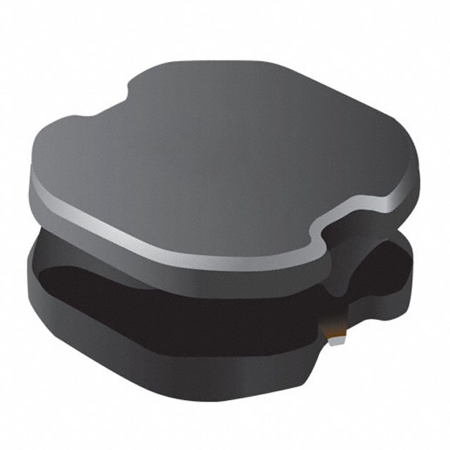
The VLP8040T-2R2N is a 2.2 µH shielded drum core wirewound inductor manufactured by TDK Corporation, rated for 6.2 A continuous current with a maximum DC resistance of 15 mOhm. This component is classified as obsolete, making equivalent substitute parts necessary for new designs and ongoing production requirements. The part operates across the industrial temperature range of -40°C to 105°C and is suitable for surface mount applications in power conversion and filtering circuits.
Substiute Parts
Key Parameters
| Parameter | Value |
|---|---|
| Inductance | 2.2 µH |
| Current Rating | 6.2 A |
| DC Resistance (DCR) | 15 mOhm Max |
| Saturation Current (Isat) | 6.7 A |
| Core Material | Ferrite |
| Shielding | Shielded |
| Tolerance | ±30% |
| Operating Temperature | -40°C ~ 105°C |
| Mounting Type | Surface Mount |
| Package Type | Nonstandard |
| Size | 8.70mm L x 8.60mm W x 4.00mm H |
Substitute Part Grouping Explanation
Substitute parts for the VLP8040T-2R2N are selected based on the following critical parameters that determine functional equivalence:
Primary Matching Criteria:
- Inductance value: 2.2 µH (exact match required)
- Inductance tolerance: ±30% (matching tolerance band)
- Core material: Ferrite (maintains magnetic properties)
- Mounting type: Surface mount (PCB compatibility)
- Inductance test frequency: 100 kHz (measurement standard)
Secondary Compatibility Factors:
- Current rating: Minimum 6.2 A (or higher for margin)
- DC resistance: 15 mOhm or lower (thermal performance)
- Operating temperature range: Minimum -40°C to 105°C coverage
- Saturation current: Minimum 6.7 A (circuit protection margin)
- Shielding type: Shielded or semi-shielded (EMI containment)
Two substitute parts meet these criteria with documented compatibility:
- VLS6045EX-2R2N (TDK Corporation) – Smaller footprint alternative with reduced current rating
- SRN8040-2R2Y (Bourns Inc.) – Direct performance upgrade with enhanced specifications
Parameter Comparison
| Parameter | VLP8040T-2R2N (Main) | VLS6045EX-2R2N (Substitute) | SRN8040-2R2Y (Substitute) |
|---|---|---|---|
| Manufacturer | TDK Corporation | TDK Corporation | Bourns Inc. |
| Inductance | 2.2 µH | 2.2 µH | 2.2 µH |
| Tolerance | ±30% | ±30% | ±30% |
| Current Rating (Amps) | 6.2 A | 5.1 A | 6.3 A |
| Saturation Current (Isat) | 6.7 A | 7.5 A | 7.4 A |
| DC Resistance (DCR) | 15 mOhm Max | 19 mOhm | 13 mOhm Max |
| Core Material | Ferrite | Ferrite | Ferrite |
| Shielding | Shielded | Shielded | Semi-Shielded |
| Operating Temperature | -40°C ~ 105°C | -40°C ~ 105°C | -40°C ~ 125°C |
| Inductance Test Frequency | 100 kHz | 100 kHz | 100 kHz |
| Mounting Type | Surface Mount | Surface Mount | Surface Mount |
| Size (L x W x H) | 8.70mm x 8.60mm x 4.00mm | 6.00mm x 6.00mm x 4.50mm | 8.00mm x 8.00mm x 4.00mm |
| Product Status | Obsolete | Active | Active |
| RoHS Status | Not specified | ROHS3 Compliant | ROHS3 Compliant |
| Moisture Sensitivity Level | 1 (Unlimited) | 1 (Unlimited) | 1 (Unlimited) |
| REACH Status | REACH Unaffected | REACH Unaffected | REACH Unaffected |
Engineering Selection Recommendations
VLS6045EX-2R2N Selection Criteria:
This TDK substitute is appropriate for applications where PCB space constraints are the primary design driver. The reduced footprint (6.00mm x 6.00mm versus 8.70mm x 8.60mm) enables higher component density. However, the current rating of 5.1 A is lower than the original 6.2 A specification. This part is suitable only for circuits where the maximum continuous current requirement does not exceed 5.1 A. The DC resistance of 19 mOhm (versus 15 mOhm maximum on the original) results in increased power dissipation. Both parts maintain identical inductance values, tolerance bands, and operating temperature ranges. ROHS3 compliance and active product status ensure long-term availability.
SRN8040-2R2Y Selection Criteria:
This Bourns substitute provides performance enhancement across multiple parameters. The current rating of 6.3 A exceeds the original 6.2 A specification, providing operational margin. The DC resistance of 13 mOhm maximum is superior to the original 15 mOhm maximum, reducing thermal losses. The extended operating temperature range (-40°C to 125°C) provides additional thermal headroom compared to the original -40°C to 105°C range. The semi-shielded construction maintains EMI containment suitable for power conversion applications. Footprint dimensions (8.00mm x 8.00mm) are compatible with the original 8.70mm x 8.60mm layout with minimal PCB redesign. ROHS3 compliance and active product status ensure supply chain continuity.
Frequently Asked Questions (FAQ)
Q: Can VLS6045EX-2R2N be used as a direct replacement for VLP8040T-2R2N in all applications?
A: No. The VLS6045EX-2R2N has a lower current rating of 5.1 A compared to the original 6.2 A. Use this substitute only in circuits where the maximum continuous current does not exceed 5.1 A. The reduced footprint makes it suitable for space-constrained designs that operate within this current limit.
Q: What are the thermal implications of using VLS6045EX-2R2N?
A: The VLS6045EX-2R2N has a DC resistance of 19 mOhm compared to 15 mOhm maximum on the original part. At equivalent current levels, this results in higher power dissipation (P = I²R). For a 5 A load, the difference is approximately 0.5 W additional dissipation. Verify thermal management in your application.
Q: Is SRN8040-2R2Y a superior replacement?
A: SRN8040-2R2Y offers performance improvements: 6.3 A current rating (versus 6.2 A), 13 mOhm maximum DC resistance (versus 15 mOhm), and extended temperature range to 125°C. The semi-shielded construction differs from the fully shielded original. Footprint dimensions are slightly smaller (8.00mm x 8.00mm versus 8.70mm x 8.60mm), requiring minimal PCB layout adjustment.
Q: Are both substitutes RoHS compliant?
A: Yes. Both VLS6045EX-2R2N and SRN8040-2R2Y are ROHS3 compliant. The original VLP8040T-2R2N does not specify RoHS status. Both substitutes are REACH unaffected and carry MSL 1 (unlimited) moisture sensitivity ratings.
Q: What is the difference between shielded and semi-shielded construction?
A: Shielded inductors (VLP8040T-2R2N and VLS6045EX-2R2N) provide complete magnetic field containment, minimizing EMI coupling to adjacent components. Semi-shielded inductors (SRN8040-2R2Y) provide partial field containment with slightly lower EMI performance but may offer cost or size advantages. Both are suitable for power conversion applications; verify EMI requirements for your specific circuit.
Q: Can I use either substitute interchangeably?
A: No. Selection depends on your circuit requirements. Use VLS6045EX-2R2N only if current does not exceed 5.1 A and space is constrained. Use SRN8040-2R2Y for applications requiring the full 6.2+ A current rating or extended temperature operation. Both maintain the 2.2 µH inductance value and ±30% tolerance required for circuit function.
Q: What packaging formats are available for these substitutes?
A: VLS6045EX-2R2N is supplied in Cut Tape (CT) and Digi-Reel format. SRN8040-2R2Y is supplied in Tape & Reel (TR) format. Confirm packaging compatibility with your procurement and assembly processes.
Alternative Parts

SJ6012L2TP
Littelfuse Inc.
6 Alternative Parts

JMK107BBJ476MA-RE
Taiyo Yuden
10 Alternative Parts

GMK107BBJ475MA-T
Taiyo Yuden
5 Alternative Parts
SJ6020N2ARP
Littelfuse Inc.
3 Alternative Parts
SJ6025R2ATP
Littelfuse Inc.
4 Alternative Parts

2474-05L
API Delevan Inc.
1 Alternative Parts

4590R-684K
API Delevan Inc.
1 Alternative Parts

CM6560R-334
API Delevan Inc.
1 Alternative Parts

CM6460-104
API Delevan Inc.
1 Alternative Parts

5526-12
API Delevan Inc.
1 Alternative Parts