


Request Quote
(Ships tomorrow)
VLF5012ST-2R2M2R0 Equivalent & Substitute Parts
Part Overview
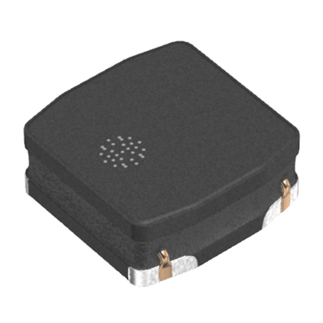
The VLF5012ST-2R2M2R0 is a 2.2 µH shielded drum core wirewound inductor manufactured by TDK Corporation, rated for 2 A continuous current with a maximum DC resistance of 83 mOhm. This surface mount component operates across the temperature range of -40°C to 105°C and is designed for applications requiring compact, shielded inductive filtering and energy storage.
The VLF5012ST-2R2M2R0 has reached obsolete product status. Identifying equivalent substitute parts is necessary to maintain design continuity, ensure supply chain availability, and support ongoing production requirements for systems currently utilizing this component.
Substiute Parts
Key Parameters
| Parameter | Value |
|---|---|
| Inductance | 2.2 µH |
| Inductance Tolerance | ±20% |
| Current Rating | 2 A |
| Current - Saturation (Isat) | 2.4 A |
| DC Resistance (DCR) Maximum | 83 mOhm |
| Shielding | Shielded |
| Core Material | Ferrite |
| Type | Drum Core, Wirewound |
| Mounting Type | Surface Mount |
| Operating Temperature Range | -40°C to 105°C |
| Inductance Test Frequency | 1 MHz |
| Moisture Sensitivity Level | MSL 1 (Unlimited) |
Substitute Part Grouping Explanation
Substitution eligibility for the VLF5012ST-2R2M2R0 is determined by the following critical parameters:
- Inductance Value: Must be 2.2 µH with tolerance of ±20% or tighter
- Current Rating: Must meet or exceed 2 A continuous current capability
- DC Resistance: Must not exceed 83 mOhm maximum
- Shielding: Must be shielded construction
- Core Type: Drum core, wirewound configuration
- Mounting: Surface mount technology
- Operating Temperature: Must support -40°C to 105°C range
- Moisture Sensitivity: MSL 1 classification required
Three substitute parts meet these criteria: VLS3012HBX-2R2M, VLS4012ET-2R2M, and SRR4018-2R2Y. Each maintains the core electrical specifications while offering different performance characteristics in current handling, DC resistance, and product lifecycle status.
Parameter Comparison
| Parameter | VLF5012ST-2R2M2R0 | VLS3012HBX-2R2M | VLS4012ET-2R2M | SRR4018-2R2Y |
|---|---|---|---|---|
| Manufacturer | TDK Corporation | TDK Corporation | TDK Corporation | Bourns Inc. |
| Inductance | 2.2 µH | 2.2 µH | 2.2 µH | 2.2 µH |
| Inductance Tolerance | ±20% | ±20% | ±20% | ±30% |
| Current Rating (Amps) | 2 A | 3.15 A | 1.7 A | 2.1 A |
| Current - Saturation (Isat) | 2.4 A | 3.35 A | 1.7 A | 2.1 A |
| DC Resistance (DCR) Maximum | 83 mOhm | 106 mOhm | 81 mOhm | 55 mOhm |
| Core Material | Ferrite | Metal | Ferrite | Ferrite |
| Shielding | Shielded | Shielded | Shielded | Shielded |
| Type | Drum Core, Wirewound | Drum Core, Wirewound | Drum Core, Wirewound | Drum Core, Wirewound |
| Mounting Type | Surface Mount | Surface Mount | Surface Mount | Surface Mount |
| Operating Temperature Range | -40°C to 105°C | -40°C to 105°C | -40°C to 105°C | -40°C to 125°C |
| Inductance Test Frequency | 1 MHz | 1 MHz | 1 MHz | 100 kHz |
| Moisture Sensitivity Level | MSL 1 | MSL 1 | MSL 1 | MSL 1 |
| Product Status | Obsolete | Active | Not For New Designs | Active |
| RoHS Status | Not specified | ROHS3 Compliant | ROHS3 Compliant | ROHS3 Compliant |
Engineering Selection Recommendations
VLS3012HBX-2R2M is the primary recommended substitute. This TDK part maintains identical inductance and tolerance specifications while providing enhanced current handling at 3.15 A, exceeding the original 2 A requirement. The component carries active product status with ROHS3 compliance, ensuring long-term availability and regulatory alignment. The metal core construction offers superior current capacity. Higher DC resistance of 106 mOhm versus 83 mOhm represents a trade-off acceptable for applications where thermal dissipation is not critical.
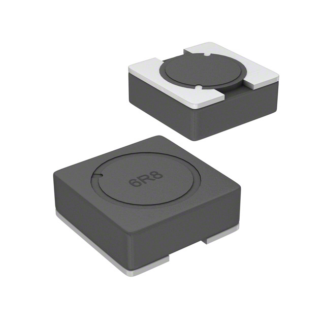
SRR4018-2R2Y from Bourns Inc. is an alternative substitute suitable for designs where lower DC resistance is prioritized. At 55 mOhm maximum, this part provides the lowest resistive losses among available options. Active product status and extended operating temperature range to 125°C support demanding thermal environments. The ±30% inductance tolerance is wider than the original specification and requires circuit validation. The 100 kHz test frequency differs from the 1 MHz standard.
VLS4012ET-2R2M is not recommended as a primary substitute. Although it maintains ferrite core construction and low DC resistance of 81 mOhm, the 1.7 A current rating falls below the original 2 A specification. Additionally, this part carries "Not For New Designs" status, limiting its suitability for ongoing production applications.
Frequently Asked Questions (FAQ)
Q: Can VLS3012HBX-2R2M directly replace VLF5012ST-2R2M2R0 in existing designs?
A: Yes, for applications where the 2 A current requirement is not exceeded. The VLS3012HBX-2R2M maintains the same 2.2 µH inductance, ±20% tolerance, shielded drum core construction, and surface mount configuration. The higher current rating of 3.15 A provides design margin. The metal core material and increased DC resistance should be evaluated for thermal performance in the specific application.
Q: What is the significance of the different core materials between VLF5012ST-2R2M2R0 (ferrite) and VLS3012HBX-2R2M (metal)?
A: Core material affects saturation characteristics, frequency response, and thermal behavior. Ferrite cores typically exhibit sharper saturation curves, while metal cores provide more gradual saturation and higher current capacity. Both materials are suitable for shielded drum core inductors at 2.2 µH. Application-specific testing is required if EMI performance or saturation behavior is critical.
Q: Why does SRR4018-2R2Y have a different inductance test frequency (100 kHz vs. 1 MHz)?
A: Inductance values can vary slightly with measurement frequency due to core material properties. The 100 kHz test frequency for SRR4018-2R2Y versus 1 MHz for the original part may result in minor inductance variations. For applications sensitive to frequency-dependent inductance behavior, circuit simulation or bench testing is recommended.
Q: Is the higher DC resistance of VLS3012HBX-2R2M (106 mOhm vs. 83 mOhm) a concern?
A: The 23 mOhm increase in DC resistance results in proportionally higher I²R losses. At 2 A continuous current, this represents approximately 0.084 W additional dissipation. Thermal analysis of the PCB layout and ambient conditions determines acceptability. For low-power filtering applications, this difference is typically negligible.
Q: Can VLS4012ET-2R2M be used if current demand is below 1.7 A?
A: Electrically, yes, provided current remains below 1.7 A saturation. However, the "Not For New Designs" status indicates TDK has discontinued active support. For new production or long-term supply assurance, VLS3012HBX-2R2M or SRR4018-2R2Y are preferred.
Q: What packaging format should be specified when ordering substitute parts?
A: VLS3012HBX-2R2M and VLS4012ET-2R2M are supplied in Tape & Reel (TR) format. SRR4018-2R2Y is also available in Tape & Reel. Confirm packaging requirements with procurement to ensure compatibility with assembly equipment and inventory management systems.
Alternative Parts

SJ6012L2TP
Littelfuse Inc.
6 Alternative Parts

JMK107BBJ476MA-RE
Taiyo Yuden
10 Alternative Parts

GMK107BBJ475MA-T
Taiyo Yuden
5 Alternative Parts
SJ6020N2ARP
Littelfuse Inc.
3 Alternative Parts
SJ6025R2ATP
Littelfuse Inc.
4 Alternative Parts

2474-05L
API Delevan Inc.
1 Alternative Parts

4590R-684K
API Delevan Inc.
1 Alternative Parts

CM6560R-334
API Delevan Inc.
1 Alternative Parts

CM6460-104
API Delevan Inc.
1 Alternative Parts

5526-12
API Delevan Inc.
1 Alternative Parts