


Request Quote
(Ships tomorrow)
UP2UC-330-R Equivalent & Substitute Parts Reference
Part Overview
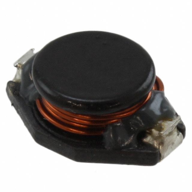
The UP2UC-330-R is a 33 µH unshielded wirewound inductor manufactured by Eaton - Electronics Division, part of the UNI-PAC™ 2UC series. This surface mount component is rated for 2.1 A continuous current with a maximum DC resistance of 100 mOhm and operates across the temperature range of -25°C to 85°C. The component is RoHS Compliant and carries an MSL rating of 1 (Unlimited), indicating minimal moisture sensitivity.
Substitute parts are identified when equivalent inductance values, current ratings, and electrical characteristics align within acceptable engineering tolerances for the application. Alternative sources provide extended temperature ranges, improved availability, or alternative packaging configurations while maintaining core electrical performance.
Substiute Parts
Key Parameters
| Parameter | Value | Unit | Significance for Substitution |
|---|---|---|---|
| Inductance | 33 | µH | Primary electrical specification; must match exactly |
| Current Rating | 2.1 | A | Determines thermal and saturation performance; substitutes must meet or exceed |
| DC Resistance (DCR) | 100 | mOhm Max | Affects power dissipation and efficiency; lower values preferred |
| Inductance Tolerance | ±20% | % | Acceptable variation range for circuit operation |
| Operating Temperature | -25 to 85 | °C | Application environment compatibility |
| Shielding | Unshielded | — | EMI characteristics and board layout considerations |
| Mounting Type | Surface Mount | — | PCB assembly compatibility |
| RoHS Status | RoHS Compliant | — | Regulatory compliance requirement |
Substitute Part Grouping Explanation
Substitution eligibility for the UP2UC-330-R is determined by the following criteria:
Primary Electrical Criteria:
- Inductance value must be 33 µH
- Current rating must be sufficient for the application (minimum 2.0 A acceptable; 2.1 A preferred)
- DC resistance must not exceed 120 mOhm to maintain acceptable power dissipation characteristics
- Inductance tolerance must be ±20% or tighter
Physical & Environmental Criteria:
- Mounting type must be Surface Mount
- Shielding configuration must be Unshielded
- Operating temperature range must encompass the application requirements
- Package dimensions must be compatible with PCB layout constraints
Compliance Criteria:
- RoHS compliance status must be RoHS Compliant or ROHS3 Compliant
- MSL rating must be 1 (Unlimited) or equivalent
The identified substitute parts meet these criteria while offering variations in current saturation characteristics, temperature operating ranges, and packaging formats.
Parameter Comparison
| Parameter | UP2UC-330-R (Eaton) | P0751.333NLT (Pulse Electronics) | SDR1005-330KL (Bourns Inc.) |
|---|---|---|---|
| Inductance | 33 µH | 33 µH | 33 µH |
| Inductance Tolerance | ±20% | ±20% | ±10% |
| Current Rating | 2.1 A | 2.0 A | 1.8 A |
| Current - Saturation (Isat) | 2 A | 2 A | 2 A |
| DC Resistance (DCR) | 100 mOhm Max | 120 mOhm Max | 120 mOhm Max |
| Shielding | Unshielded | Unshielded | Unshielded |
| Operating Temperature | -25°C to 85°C | -40°C to 130°C | -40°C to 125°C |
| Frequency - Self Resonant | 15 MHz | — | 14 MHz |
| Inductance Frequency - Test | 100 kHz | 100 kHz | 1 kHz |
| Mounting Type | Surface Mount | Surface Mount | Surface Mount |
| Size / Dimension | 0.500" L x 0.394" W (12.70mm x 10.00mm) | 0.510" L x 0.370" W (12.95mm x 9.40mm) | 0.500" L x 0.394" W (12.70mm x 10.00mm) |
| Height - Seated (Max) | 0.205" (5.21mm) | 0.215" (5.46mm) | 0.197" (5.00mm) |
| RoHS Status | RoHS Compliant | ROHS3 Compliant | ROHS3 Compliant |
| MSL Rating | 1 (Unlimited) | 1 (Unlimited) | 1 (Unlimited) |
| Product Status | Active | Active | Active |
Engineering Selection Recommendations
UP2UC-330-R (Eaton - Electronics Division)
Primary selection when the original specification is required. Offers the highest current rating (2.1 A) and lowest DC resistance (100 mOhm Max) among the three options. Operating temperature range of -25°C to 85°C is suitable for standard industrial and commercial applications. RoHS Compliant status meets regulatory requirements. Current inventory of 751 pieces supports immediate procurement.
P0751.333NLT (Pulse Electronics)
Suitable substitute when extended temperature operation is required, supporting -40°C to 130°C. Current rating of 2.0 A is marginally lower than the primary part but acceptable for applications not requiring the full 2.1 A specification. DC resistance of 120 mOhm Max represents a 20% increase over the primary part, resulting in proportionally higher power dissipation. ROHS3 Compliant status provides enhanced regulatory alignment. Significantly higher inventory availability (3320 pieces) supports supply chain continuity. Dimensions are slightly larger (0.510" L vs 0.500" L), requiring PCB layout verification.
SDR1005-330KL (Bourns Inc.)
Applicable when tighter inductance tolerance (±10% vs ±20%) is advantageous for circuit performance. Current rating of 1.8 A is the lowest among the three options and may be limiting for applications requiring sustained 2.0+ A operation. DC resistance of 120 mOhm Max matches the Pulse Electronics substitute. Operating temperature range of -40°C to 125°C provides extended low-temperature capability. ROHS3 Compliant status meets regulatory requirements. Ferrite drum core construction differs from wirewound design of primary part. Lowest seated height (0.197" vs 0.205") may provide PCB layout advantages. Highest inventory availability (8777 pieces) ensures supply security. Inductance test frequency of 1 kHz differs from primary part specification of 100 kHz.
Frequently Asked Questions (FAQ)
Q: Can P0751.333NLT replace UP2UC-330-R in all applications?
A: P0751.333NLT is electrically compatible for applications where the 2.0 A current rating is sufficient. The 20 mOhm increase in DC resistance (100 to 120 mOhm) results in approximately 20% higher power dissipation at rated current. Extended temperature range (-40°C to 130°C) provides broader environmental compatibility. PCB layout must accommodate the slightly larger length dimension (0.510" vs 0.500").
Q: What are the limitations of SDR1005-330KL as a substitute?
A: The 1.8 A current rating is 14% lower than the primary part's 2.1 A specification. Applications requiring sustained current above 1.8 A may experience inductor saturation or thermal stress. The ferrite drum core construction differs from the wirewound design, potentially affecting frequency response characteristics. Inductance test frequency of 1 kHz differs from the primary part's 100 kHz specification, which may result in different measured inductance values depending on circuit operating frequency.
Q: Are all three parts RoHS compliant?
A: Yes. The primary part UP2UC-330-R is RoHS Compliant. Both substitute parts P0751.333NLT and SDR1005-330KL are ROHS3 Compliant, which represents an enhanced compliance standard. All three parts carry MSL rating of 1 (Unlimited), indicating minimal moisture sensitivity during storage and handling.
Q: How do physical dimensions affect substitution?
A: The primary part UP2UC-330-R and SDR1005-330KL share identical length and width dimensions (0.500" L x 0.394" W). P0751.333NLT is slightly larger (0.510" L x 0.370" W). Height differences range from 0.197" to 0.215", which may impact PCB clearance in space-constrained designs. Verify PCB layout compatibility before substitution, particularly for P0751.333NLT.
Q: What is the significance of inductance tolerance differences?
A: The primary part and P0751.333NLT specify ±20% tolerance, while SDR1005-330KL specifies ±10% tolerance. Tighter tolerance (±10%) provides more predictable circuit performance and may be required for precision applications. Standard tolerance (±20%) is acceptable for general-purpose filtering and energy storage applications where inductance variation within this range does not affect circuit function.
Q: Can these parts be used interchangeably in high-frequency applications?
A: Self-resonant frequency specifications differ: UP2UC-330-R at 15 MHz, SDR1005-330KL at 14 MHz, and P0751.333NLT unspecified. These values indicate the frequency at which the inductor transitions from inductive to capacitive behavior. For applications operating significantly below these frequencies (typically below 5 MHz), the differences are negligible. High-frequency applications above 10 MHz require careful evaluation of self-resonant frequency specifications.
Alternative Parts

SJ6012L2TP
Littelfuse Inc.
6 Alternative Parts

JMK107BBJ476MA-RE
Taiyo Yuden
10 Alternative Parts

GMK107BBJ475MA-T
Taiyo Yuden
5 Alternative Parts
SJ6020N2ARP
Littelfuse Inc.
3 Alternative Parts
SJ6025R2ATP
Littelfuse Inc.
4 Alternative Parts

2474-05L
API Delevan Inc.
1 Alternative Parts

4590R-684K
API Delevan Inc.
1 Alternative Parts

CM6560R-334
API Delevan Inc.
1 Alternative Parts

CM6460-104
API Delevan Inc.
1 Alternative Parts

5526-12
API Delevan Inc.
1 Alternative Parts