


Request Quote
(Ships tomorrow)
UG18ACTHE3/45 Equivalent & Substitute Parts
Part Overview
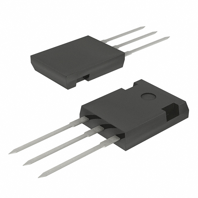
The UG18ACTHE3/45 is a diode array rectifier manufactured by Vishay General Semiconductor - Diodes Division, configured as a 1 Pair Common Cathode design rated for 50 V DC reverse voltage and 18 A average rectified current per diode. This component is packaged in a TO-220-3 through-hole configuration and is qualified to AEC-Q101 automotive standards.
The UG18ACTHE3/45 is classified as obsolete. Identifying equivalent and substitute parts is necessary to maintain design continuity, ensure supply chain availability, and support ongoing production requirements for applications utilizing this diode array configuration.
Substiute Parts
Key Parameters
| Parameter | Value |
|---|---|
| Diode Configuration | 1 Pair Common Cathode |
| Voltage - DC Reverse (Vr) (Max) | 50 V |
| Current - Average Rectified (Io) (per Diode) | 18 A |
| Voltage - Forward (Vf) (Max) @ If | 1.1 V @ 9 A |
| Speed Classification | Fast Recovery ≤ 500 ns, > 200 mA (Io) |
| Reverse Recovery Time (trr) | 30 ns |
| Current - Reverse Leakage @ Vr | 10 µA @ 50 V |
| Operating Temperature - Junction | -65°C ~ 150°C |
| Grade | Automotive |
| Qualification | AEC-Q101 |
| Mounting Type | Through Hole |
| Package / Case | TO-220-3 |
| RoHS Status | ROHS3 Compliant |
| Moisture Sensitivity Level (MSL) | 1 (Unlimited) |
Substitute Part Grouping Explanation
Substitution of the UG18ACTHE3/45 is determined by electrical and mechanical compatibility across the following critical parameters:
Electrical Compatibility Criteria:
- Diode configuration must remain 1 Pair Common Cathode
- DC reverse voltage rating must equal or exceed 50 V
- Average rectified current per diode must equal or exceed 18 A
- Forward voltage characteristics must be compatible with circuit design
- Speed classification must maintain Fast Recovery characteristics
- Reverse recovery time must support circuit switching requirements
- Reverse leakage current must not exceed application limits
Mechanical Compatibility Criteria:
- Mounting type must be Through Hole
- Package footprint must be compatible with PCB layout
- Operating temperature range must support application environment
Compliance Criteria:
- Automotive grade qualification (AEC-Q101) must be maintained
- RoHS3 compliance must be preserved
- MSL rating must support manufacturing processes
The SR2050PTHC0G meets these substitution criteria through equivalent electrical ratings, matching automotive qualification, and compatible through-hole mounting.
Parameter Comparison
| Parameter | UG18ACTHE3/45 (Main Part) | SR2050PTHC0G (Substitute) |
|---|---|---|
| Manufacturer | Vishay General Semiconductor - Diodes Division | Taiwan Semiconductor Corporation |
| Product Status | Obsolete | Active |
| Diode Configuration | 1 Pair Common Cathode | 1 Pair Common Cathode |
| Voltage - DC Reverse (Vr) (Max) | 50 V | 50 V |
| Current - Average Rectified (Io) (per Diode) | 18 A | 20 A |
| Voltage - Forward (Vf) (Max) @ If | 1.1 V @ 9 A | 700 mV @ 10 A |
| Speed Classification | Fast Recovery ≤ 500 ns, > 200 mA (Io) | Fast Recovery ≤ 500 ns, > 200 mA (Io) |
| Current - Reverse Leakage @ Vr | 10 µA @ 50 V | 500 µA @ 50 V |
| Operating Temperature - Junction | -65°C ~ 150°C | -55°C ~ 150°C |
| Grade | Automotive | Automotive |
| Qualification | AEC-Q101 | AEC-Q101 |
| Mounting Type | Through Hole | Through Hole |
| Package / Case | TO-220-3 | TO-247-3 |
| RoHS Status | ROHS3 Compliant | ROHS3 Compliant |
| Moisture Sensitivity Level (MSL) | 1 (Unlimited) | 1 (Unlimited) |
Engineering Selection Recommendations
The SR2050PTHC0G is an active substitute for the obsolete UG18ACTHE3/45. Both components maintain identical automotive grade qualification (AEC-Q101) and RoHS3 compliance status, ensuring regulatory and quality standards are preserved.
The SR2050PTHC0G provides increased current capacity (20 A versus 18 A per diode), supporting applications with higher current demands while maintaining the same 50 V reverse voltage rating. The substitute exhibits lower forward voltage characteristics (700 mV @ 10 A versus 1.1 V @ 9 A), resulting in reduced power dissipation in rectification circuits.
Both components employ Fast Recovery technology with equivalent speed classifications and support identical operating temperature maximums (150°C junction temperature). The primary mechanical difference is the package transition from TO-220-3 to TO-247-3, which requires PCB layout modification but maintains through-hole mounting compatibility.
The SR2050PTHC0G is currently in active production status, ensuring long-term supply availability and manufacturing support compared to the obsolete UG18ACTHE3/45.
Frequently Asked Questions (FAQ)
Q: Can the SR2050PTHC0G directly replace the UG18ACTHE3/45 without circuit modification?
A: The SR2050PTHC0G is electrically compatible as a substitute. However, the package transition from TO-220-3 to TO-247-3 requires PCB layout modification. Both packages are through-hole configurations with different footprints and pin spacing. Circuit schematic compatibility is maintained due to identical diode configuration (1 Pair Common Cathode) and voltage ratings (50 V).
Q: What are the implications of the forward voltage difference between these parts?
A: The SR2050PTHC0G exhibits lower forward voltage (700 mV @ 10 A) compared to the UG18ACTHE3/45 (1.1 V @ 9 A). This results in reduced power dissipation during rectification. Circuits designed for the higher forward voltage of the original part will operate with improved efficiency using the substitute. No circuit redesign is required.
Q: How does the increased current rating of the SR2050PTHC0G affect substitution?
A: The SR2050PTHC0G is rated for 20 A average rectified current per diode, exceeding the UG18ACTHE3/45 specification of 18 A. This higher rating provides design margin and supports applications with increased current demands. The substitute is suitable for all applications within the original 18 A specification.
Q: Are there temperature range considerations for this substitution?
A: The UG18ACTHE3/45 operates from -65°C to 150°C junction temperature, while the SR2050PTHC0G operates from -55°C to 150°C. The substitute has a narrower low-temperature range. Applications requiring operation below -55°C junction temperature require evaluation against the substitute's minimum operating specification.
Q: What is the significance of the reverse leakage current difference?
A: The SR2050PTHC0G exhibits higher reverse leakage current (500 µA @ 50 V) compared to the UG18ACTHE3/45 (10 µA @ 50 V). This difference is within acceptable ranges for standard rectifier applications. Applications with stringent leakage requirements should evaluate this parameter against circuit specifications.
Q: Do both parts maintain automotive qualification standards?
A: Both the UG18ACTHE3/45 and SR2050PTHC0G are qualified to AEC-Q101 automotive standards and maintain ROHS3 compliance. Regulatory and quality requirements are equivalent between the original and substitute parts.
Q: What is the impact of the package change from TO-220-3 to TO-247-3?
A: The TO-247-3 package is physically larger than TO-220-3 but maintains through-hole mounting compatibility. PCB layout modification is required to accommodate the different footprint and pin spacing. Both packages support equivalent thermal performance for automotive applications.
Alternative Parts

SJ6012L2TP
Littelfuse Inc.
6 Alternative Parts

JMK107BBJ476MA-RE
Taiyo Yuden
10 Alternative Parts

GMK107BBJ475MA-T
Taiyo Yuden
5 Alternative Parts
SJ6020N2ARP
Littelfuse Inc.
3 Alternative Parts
SJ6025R2ATP
Littelfuse Inc.
4 Alternative Parts

2474-05L
API Delevan Inc.
1 Alternative Parts

4590R-684K
API Delevan Inc.
1 Alternative Parts

CM6560R-334
API Delevan Inc.
1 Alternative Parts

CM6460-104
API Delevan Inc.
1 Alternative Parts

5526-12
API Delevan Inc.
1 Alternative Parts