


Request Quote
(Ships tomorrow)
UCC28060DR Equivalent & Substitute Parts
Part Overview
The UCC28060DR is a Power Factor Correction (PFC) controller IC manufactured by Texas Instruments, designed for discontinuous (transition) mode operation at 500kHz switching frequency. This device is classified as Active product status and is widely used in power management applications requiring PFC functionality in the 8V to 21V supply voltage range.
Finding equivalent and substitute parts becomes necessary when the UCC28060DR reaches end-of-life status, inventory constraints occur, or alternative sourcing is required for cost optimization or supply chain diversification. Substitute parts must maintain compatibility across critical electrical parameters including package type, operating temperature range, and functional mode characteristics.
Substiute Parts
Key Parameters
| Parameter | Value |
|---|---|
| Manufacturer Part Number | UCC28060DR |
| Manufacturer | Texas Instruments |
| Category | Power Management (PMIC) |
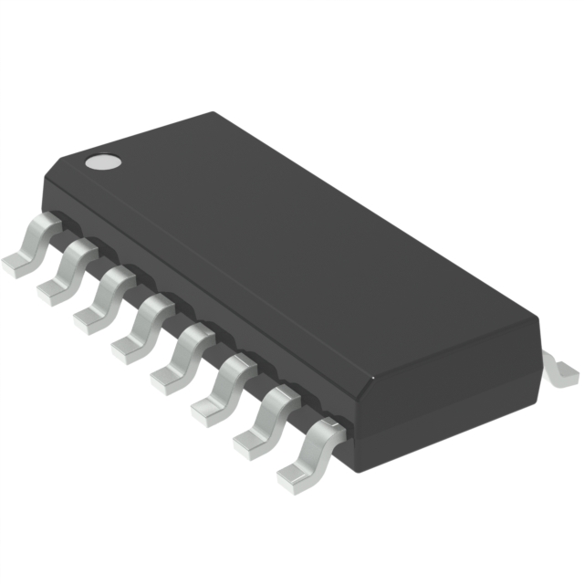
| Package / Case | 16-SOIC (0.154", 3.90mm Width) |
| Mode | Discontinuous (Transition) |
| Frequency - Switching | 500kHz |
| Voltage - Supply | 8V ~ 21V |
| Current - Startup | 200 µA |
| Operating Temperature | -40°C ~ 125°C |
| Mounting Type | Surface Mount |
| RoHS Status | ROHS3 Compliant |
| Product Status | Active |
Substitute Part Grouping Explanation
Substitution logic for PFC controller ICs is determined by the following critical parameters:
Package Compatibility: Both the main part and substitute must use the 16-SOIC package to ensure PCB layout compatibility and pin-to-pin functionality.
Operating Temperature Range: The substitute must support the full -40°C to 125°C operating temperature range to maintain performance across all environmental conditions.
Functional Mode: The substitute must support discontinuous or transition mode operation, as this determines the control algorithm and circuit behavior.
Supply Voltage Range: The substitute voltage specification must encompass or exceed the 8V to 21V range of the main part to ensure operation across all input conditions.
RoHS and Compliance Status: Both parts must maintain ROHS3 compliance and equivalent regulatory certifications (REACH, ECCN, HTSUS codes) for procurement and deployment in regulated applications.
The NCP1631DR2G is identified as a substitute part; however, critical parameter deviations exist that must be evaluated during component selection.
Parameter Comparison
| Parameter | UCC28060DR (Main Part) | NCP1631DR2G (Substitute) | Compatibility Notes |
|---|---|---|---|
| Manufacturer | Texas Instruments | onsemi | Different manufacturer |
| Package / Case | 16-SOIC (0.154", 3.90mm Width) | 16-SOIC (0.154", 3.90mm Width) | Package compatible |
| Mode | Discontinuous (Transition) | Critical Conduction (CRM), Discontinuous Conduction (DCM) | Mode overlap exists; CRM/DCM capable |
| Frequency - Switching | 500kHz | 130kHz | Significant frequency difference |
| Voltage - Supply | 8V ~ 21V | 10V ~ 15V | Voltage range narrower; 8V-10V not covered |
| Current - Startup | 200 µA | 100 µA | Lower startup current in substitute |
| Operating Temperature | -40°C ~ 125°C | -40°C ~ 125°C | Temperature range compatible |
| Mounting Type | Surface Mount | Surface Mount | Mounting type compatible |
| RoHS Status | ROHS3 Compliant | ROHS3 Compliant | Compliance compatible |
| Product Status | Active | Not For New Designs | Main part preferred for new designs |
Engineering Selection Recommendations
Primary Selection: The UCC28060DR remains the recommended choice for new designs due to its Active product status and broader supply voltage range (8V ~ 21V), which accommodates a wider range of input conditions.
Substitute Consideration: The NCP1631DR2G may be evaluated as a substitute only when the following conditions are met:
The application operates within the 10V to 15V supply voltage range, ensuring the narrower voltage specification of the substitute does not limit functionality.
The switching frequency difference (130kHz versus 500kHz) is evaluated against circuit design requirements, including EMI characteristics, transformer design, and control loop stability.
The product status designation "Not For New Designs" indicates the NCP1631DR2G is in mature or declining lifecycle phase. Use of this substitute should be limited to legacy system maintenance or supply chain contingency scenarios.
Both parts maintain equivalent RoHS3 compliance, REACH status, and regulatory certifications (ECCN: EAR99, HTSUS: 8542.39.0001), ensuring regulatory compatibility.
Frequently Asked Questions (FAQ)
Q: Can the NCP1631DR2G be used as a direct replacement for the UCC28060DR?
A: Direct replacement is not recommended without circuit evaluation. While both devices use the 16-SOIC package and support discontinuous mode operation, the NCP1631DR2G has a narrower supply voltage range (10V ~ 15V versus 8V ~ 21V) and significantly lower switching frequency (130kHz versus 500kHz). Applications operating below 10V input or requiring 500kHz operation cannot use this substitute without design modification.
Q: What is the impact of the switching frequency difference between these parts?
A: The UCC28060DR operates at 500kHz while the NCP1631DR2G operates at 130kHz. This 3.8x frequency difference affects transformer design, output filter requirements, EMI characteristics, and control loop bandwidth. Substitution requires re-evaluation of the power stage design and may necessitate component changes in the magnetic and filtering circuits.
Q: Are there any compliance or certification differences between these parts?
A: Both parts maintain ROHS3 compliance, REACH unaffected status, and identical regulatory codes (ECCN: EAR99, HTSUS: 8542.39.0001). No compliance barriers exist for substitution from a regulatory perspective.
Q: Why is the NCP1631DR2G marked "Not For New Designs"?
A: This designation indicates the part is in mature or end-of-life phase and is not recommended for new product development. The UCC28060DR, with Active status, is the preferred choice for new designs. The NCP1631DR2G should be reserved for legacy system support or temporary supply contingency only.
Q: What is the significance of the startup current difference (200 µA versus 100 µA)?
A: The lower startup current of the NCP1631DR2G (100 µA) may reduce inrush current during power-on but does not affect steady-state operation. This parameter is typically non-critical for substitution decisions unless the application has specific startup current constraints.
Q: Can both parts be used interchangeably in the same PCB layout?
A: Yes, from a physical package perspective. Both use the 16-SOIC package with identical pin spacing (0.154", 3.90mm width). However, electrical parameter differences require circuit validation before substitution, particularly regarding supply voltage range and switching frequency compatibility.
Alternative Parts

SJ6012L2TP
Littelfuse Inc.
6 Alternative Parts

JMK107BBJ476MA-RE
Taiyo Yuden
10 Alternative Parts

GMK107BBJ475MA-T
Taiyo Yuden
5 Alternative Parts
SJ6020N2ARP
Littelfuse Inc.
3 Alternative Parts
SJ6025R2ATP
Littelfuse Inc.
4 Alternative Parts

2474-05L
API Delevan Inc.
1 Alternative Parts

4590R-684K
API Delevan Inc.
1 Alternative Parts

CM6560R-334
API Delevan Inc.
1 Alternative Parts

CM6460-104
API Delevan Inc.
1 Alternative Parts

5526-12
API Delevan Inc.
1 Alternative Parts