


Request Quote
(Ships tomorrow)
TSM4NB65CP Equivalent & Substitute Parts
Part Overview
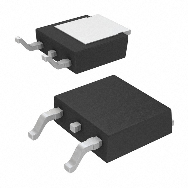
The TSM4NB65CP is an N-Channel power MOSFET manufactured by Taiwan Semiconductor Corporation, rated for 650V drain-to-source voltage with 4A continuous drain current at 25°C. The device is housed in a TO-252 (DPAK) surface mount package and is designed for high-voltage switching applications requiring 50W maximum power dissipation. The part maintains Active product status and is RoHS3 compliant. Equivalent and substitute parts are identified to support procurement flexibility, inventory management, and supply chain continuity when the primary part becomes unavailable or when design requirements necessitate alternative specifications within compatible electrical and mechanical parameters.
Substiute Parts
Key Parameters
| Parameter | Value | Unit |
|---|---|---|
| Drain to Source Voltage (Vdss) | 650 | V |
| Continuous Drain Current (Id) @ 25°C | 4 | A |
| Drive Voltage (Max Rds On) | 10 | V |
| Rds On (Max) @ Id, Vgs | 3.37 | Ohm @ 2A, 10V |
| Gate Threshold Voltage (Vgs(th)) (Max) | 4.5 | V @ 250µA |
| Gate Charge (Qg) (Max) | 13.46 | nC @ 10V |
| Maximum Gate Voltage (Vgs) | ±30 | V |
| Input Capacitance (Ciss) (Max) | 549 | pF @ 25V |
| Power Dissipation (Max) | 50 | W |
| Operating Temperature Range | -55 to 150 | °C |
| Mounting Type | Surface Mount | — |
| Package / Case | TO-252-3, DPAK | — |
| FET Type | N-Channel | — |
| Technology | MOSFET (Metal Oxide) | — |
Substitute Part Grouping Explanation
Substitute parts for the TSM4NB65CP are identified based on strict electrical and mechanical compatibility criteria. The primary substitution logic is governed by the following parameters:
Mandatory Compatibility Parameters:
- FET Type: N-Channel
- Technology: MOSFET (Metal Oxide)
- Mounting Type: Surface Mount
- Package / Case: TO-252-3, DPAK (2 Leads + Tab), SC-63
- Operating Temperature Range: -55°C to 150°C (TJ)
- RoHS3 Compliance: Required
Electrical Performance Parameters (Allowable Variance):
- Drain to Source Voltage (Vdss): Equal to or greater than 650V
- Continuous Drain Current (Id) @ 25°C: Equal to or greater than 4A
- Drive Voltage: 10V nominal
- Gate Threshold Voltage (Vgs(th)): Within acceptable switching characteristics
- Power Dissipation: Equal to or greater than 50W
The SPD02N80C3ATMA1 from Infineon Technologies qualifies as a substitute part. While it exhibits a higher Vdss rating (800V) and lower continuous drain current (2A), it maintains the same surface mount TO-252-3 package configuration, operates within the identical temperature range, and meets RoHS3 compliance requirements. The higher voltage rating provides additional design margin for overvoltage protection, and the lower current rating reflects a different application profile within the same package family.
Parameter Comparison
| Parameter | TSM4NB65CP (Main Part) | SPD02N80C3ATMA1 (Substitute) | Unit |
|---|---|---|---|
| Manufacturer | Taiwan Semiconductor Corporation | Infineon Technologies | — |
| FET Type | N-Channel | N-Channel | — |
| Technology | MOSFET (Metal Oxide) | MOSFET (Metal Oxide) | — |
| Drain to Source Voltage (Vdss) | 650 | 800 | V |
| Continuous Drain Current (Id) @ 25°C | 4 | 2 | A |
| Drive Voltage (Max Rds On) | 10 | 10 | V |
| Rds On (Max) @ Id, Vgs | 3.37 @ 2A, 10V | 2.7 @ 1.2A, 10V | Ohm |
| Gate Threshold Voltage (Vgs(th)) (Max) | 4.5 @ 250µA | 3.9 @ 120µA | V |
| Gate Charge (Qg) (Max) | 13.46 @ 10V | 16 @ 10V | nC |
| Maximum Gate Voltage (Vgs) | ±30 | ±20 | V |
| Input Capacitance (Ciss) (Max) | 549 @ 25V | 290 @ 100V | pF |
| Power Dissipation (Max) | 50 | 42 | W |
| Operating Temperature Range | -55 to 150 | -55 to 150 | °C |
| Mounting Type | Surface Mount | Surface Mount | — |
| Package / Case | TO-252-3, DPAK | TO-252-3, DPAK | — |
| RoHS Status | ROHS3 Compliant | ROHS3 Compliant | — |
| REACH Status | REACH Unaffected | REACH Unaffected | — |
| ECCN | EAR99 | EAR99 | — |
| HTSUS Code | 8541.29.0095 | 8541.29.0095 | — |
Engineering Selection Recommendations
TSM4NB65CP (Primary Part): The TSM4NB65CP is the specified component for applications requiring 650V blocking voltage with 4A continuous drain current. This part is Active in product status with 2200 pieces in current inventory. Selection of this part is appropriate for designs operating at or near the 650V voltage specification with current demands at or above 4A. The device meets all regulatory requirements including RoHS3 compliance and REACH unaffected status.
SPD02N80C3ATMA1 (Substitute Part): The SPD02N80C3ATMA1 from Infineon Technologies serves as a substitute for applications where higher voltage margin is required or where the lower 2A current rating is acceptable. The 800V Vdss rating provides additional overvoltage protection headroom. This part is Active in product status with 9942 pieces in current inventory. The substitute maintains identical package configuration (TO-252-3, DPAK), operating temperature range (-55°C to 150°C), and regulatory compliance (RoHS3, REACH unaffected, EAR99). Selection of this substitute is appropriate when design requirements permit the lower continuous drain current specification or when higher voltage blocking capability is beneficial.
Both parts are suitable for direct PCB footprint compatibility and require no layout modifications. Component selection between the main part and substitute depends on circuit current requirements and voltage margin specifications.
Frequently Asked Questions (FAQ)
Q: Can the SPD02N80C3ATMA1 directly replace the TSM4NB65CP in existing designs?
A: Direct PCB footprint replacement is possible due to identical TO-252-3 (DPAK) package configuration. However, circuit-level compatibility depends on current requirements. The SPD02N80C3ATMA1 is rated for 2A continuous drain current compared to the TSM4NB65CP's 4A rating. Designs operating at or below 2A drain current can use the substitute without modification. Designs requiring current above 2A must be re-evaluated for the lower current rating.
Q: What are the key electrical differences between these parts?
A: The TSM4NB65CP operates at 650V Vdss with 4A continuous drain current. The SPD02N80C3ATMA1 operates at 800V Vdss with 2A continuous drain current. The substitute provides higher voltage blocking capability but lower current capacity. Both devices share identical 10V drive voltage specification and operate across the same temperature range (-55°C to 150°C).
Q: Are both parts RoHS3 compliant?
A: Yes. Both the TSM4NB65CP and SPD02N80C3ATMA1 are RoHS3 compliant and REACH unaffected. Both carry EAR99 export classification and share the same HTSUS code (8541.29.0095).
Q: What is the impact of the different gate charge specifications?
A: The TSM4NB65CP has a maximum gate charge of 13.46 nC at 10V, while the SPD02N80C3ATMA1 has 16 nC at 10V. The substitute requires slightly higher gate charge for switching operations. Gate driver circuits must supply sufficient charge to fully enhance the device. This difference may affect switching speed and driver power consumption but does not prevent substitution in most applications.
Q: How do the on-resistance specifications compare?
A: The TSM4NB65CP exhibits 3.37 Ohm maximum on-resistance at 2A and 10V gate voltage. The SPD02N80C3ATMA1 exhibits 2.7 Ohm maximum on-resistance at 1.2A and 10V gate voltage. The substitute has lower on-resistance, resulting in reduced conduction losses at equivalent current levels. This characteristic is beneficial for thermal management in power applications.
Q: Are there any gate voltage limitations when substituting?
A: The TSM4NB65CP permits maximum gate voltage of ±30V. The SPD02N80C3ATMA1 permits maximum gate voltage of ±20V. Gate driver circuits must be designed to operate within the ±20V limit when using the substitute part. Existing designs using gate voltages above ±20V require modification before substitution.
Q: What is the significance of the different input capacitance values?
A: The TSM4NB65CP has input capacitance of 549 pF at 25V. The SPD02N80C3ATMA1 has input capacitance of 290 pF at 100V. The lower input capacitance of the substitute results in faster switching transitions and reduced gate driver current requirements. This characteristic may improve overall circuit efficiency and reduce electromagnetic interference.
Q: Can both parts be used interchangeably in high-frequency switching applications?
A: Both parts are suitable for high-frequency switching applications. The SPD02N80C3ATMA1's lower input capacitance and gate charge provide advantages in high-frequency operation by reducing switching losses. However, current rating limitations of the substitute must be observed. Applications requiring 4A continuous current must use the TSM4NB65CP.
Alternative Parts

SJ6012L2TP
Littelfuse Inc.
6 Alternative Parts

JMK107BBJ476MA-RE
Taiyo Yuden
10 Alternative Parts

GMK107BBJ475MA-T
Taiyo Yuden
5 Alternative Parts
SJ6020N2ARP
Littelfuse Inc.
3 Alternative Parts
SJ6025R2ATP
Littelfuse Inc.
4 Alternative Parts

2474-05L
API Delevan Inc.
1 Alternative Parts

4590R-684K
API Delevan Inc.
1 Alternative Parts

CM6560R-334
API Delevan Inc.
1 Alternative Parts

CM6460-104
API Delevan Inc.
1 Alternative Parts

5526-12
API Delevan Inc.
1 Alternative Parts