


Request Quote
(Ships tomorrow)
TLC274IDR Equivalent & Substitute Parts
Part Overview
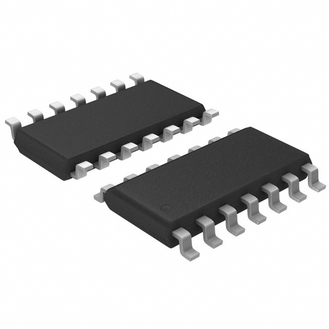
The TLC274IDR is a general-purpose operational amplifier manufactured by Texas Instruments, featuring four independent circuits in a 14-SOIC surface-mount package. This device is classified as Active product status and is RoHS3 compliant. The TLC274IDR serves applications requiring moderate bandwidth and low input bias current characteristics. Substitute parts are identified when equivalent electrical performance and mechanical compatibility are required due to inventory constraints, manufacturing discontinuation, or design optimization needs.
Substiute Parts
Key Parameters
| Parameter | Value | Unit |
|---|---|---|
| Manufacturer Part Number | TLC274IDR | — |
| Manufacturer | Texas Instruments | — |
| Number of Circuits | 4 | — |
| Amplifier Type | General Purpose | — |
| Package / Case | 14-SOIC (0.154", 3.90mm Width) | — |
| Mounting Type | Surface Mount | — |
| Slew Rate | 3.6 | V/µs |
| Gain Bandwidth Product | 2.2 | MHz |
| Current - Input Bias | 0.6 | pA |
| Voltage - Input Offset | 1.1 | mV |
| Current - Supply | 2.7 | mA (x4 Channels) |
| Current - Output / Channel | 30 | mA |
| Voltage - Supply Span (Min) | 4 | V |
| Voltage - Supply Span (Max) | 16 | V |
| Operating Temperature | -40 to 85 | °C |
| RoHS Status | ROHS3 Compliant | — |
| Moisture Sensitivity Level (MSL) | 1 (Unlimited) | — |
Substitute Part Grouping Explanation
Substitution eligibility for the TLC274IDR is determined by the following criteria:
Mechanical Compatibility: All substitute parts must use the 14-SOIC (0.154", 3.90mm Width) surface-mount package to ensure PCB footprint compatibility without redesign.
Electrical Compatibility: Substitute parts must operate within the supply voltage range of 4V to 16V minimum and maximum specifications. The TLC274IDR operates at -40°C to 85°C; substitutes operating at wider temperature ranges (-40°C to 125°C) are acceptable for applications within the original temperature window.
Circuit Configuration: All substitute parts contain four independent amplifier circuits, maintaining functional equivalence for quad-amplifier applications.
Key Differentiating Parameters: Slew rate, gain bandwidth product, input bias current, supply current, and output current per channel are the primary electrical parameters that distinguish substitute options. Substitutes are grouped based on whether these parameters meet or exceed the original specification requirements.
Compliance: All substitute parts maintain RoHS3 compliance, MSL Level 1 rating, and Active product status, ensuring regulatory and manufacturing process compatibility.
Parameter Comparison
| Parameter | TLC274IDR (Main) | TS274CDT | TS274IDT | TS27L4AIDT | TS27L4CDT | TS27L4IDT | TS27M4IDT |
|---|---|---|---|---|---|---|---|
| Manufacturer | Texas Instruments | STMicroelectronics | STMicroelectronics | STMicroelectronics | STMicroelectronics | STMicroelectronics | STMicroelectronics |
| Amplifier Type | General Purpose | CMOS | CMOS | CMOS | CMOS | CMOS | CMOS |
| Number of Circuits | 4 | 4 | 4 | 4 | 4 | 4 | 4 |
| Package / Case | 14-SOIC | 14-SOIC | 14-SOIC | 14-SOIC | 14-SOIC | 14-SOIC | 14-SOIC |
| Slew Rate (V/µs) | 3.6 | 5.5 | 5.5 | 0.04 | 0.04 | 0.04 | 0.6 |
| Gain Bandwidth Product (MHz) | 2.2 | 3.5 | 3.5 | 0.1 | 0.1 | 0.1 | 1 |
| Current - Input Bias (pA) | 0.6 | 1 | 1 | 1 | 1 | 1 | 1 |
| Voltage - Input Offset (mV) | 1.1 | 1.1 | 1.1 | 0.9 | 1.1 | 1.1 | 1.1 |
| Current - Supply (mA) | 2.7 | 1 | 1 | 0.01 | 0.01 | 0.01 | 0.15 |
| Current - Output / Channel (mA) | 30 | 45 | 45 | 45 | 45 | 45 | 45 |
| Voltage - Supply Span (Min - Max) | 4 to 16 | 3 to 16 | 3 to 16 | 3 to 16 | 3 to 16 | 3 to 16 | 3 to 16 |
| Operating Temperature (°C) | -40 to 85 | 0 to 70 | -40 to 125 | -40 to 125 | 0 to 70 | -40 to 125 | -40 to 125 |
| RoHS Status | ROHS3 Compliant | ROHS3 Compliant | ROHS3 Compliant | ROHS3 Compliant | ROHS3 Compliant | ROHS3 Compliant | ROHS3 Compliant |
| MSL Rating | 1 (Unlimited) | 1 (Unlimited) | 1 (Unlimited) | 1 (Unlimited) | 1 (Unlimited) | 1 (Unlimited) | 1 (Unlimited) |
Engineering Selection Recommendations
TS274CDT and TS274IDT: These STMicroelectronics CMOS amplifiers provide higher slew rate (5.5 V/µs) and gain bandwidth product (3.5 MHz) compared to the TLC274IDR. Both parts operate within the TLC274IDR supply voltage range and maintain 14-SOIC package compatibility. TS274IDT extends the operating temperature range to -40°C to 125°C, providing broader environmental coverage. TS274CDT operates at 0°C to 70°C, which is narrower than the original specification. Both parts reduce supply current to 1 mA and increase output current capability to 45 mA per channel. Selection between these two depends on temperature range requirements for the application.
TS27L4AIDT and TS27L4CDT: These ultra-low-power CMOS amplifiers feature significantly reduced supply current (10 µA per channel) and lower slew rate (0.04 V/µs) with 100 kHz gain bandwidth product. These parts are suitable for battery-powered or low-power applications where the TLC274IDR's bandwidth and slew rate exceed application requirements. TS27L4AIDT operates at -40°C to 125°C, while TS27L4CDT operates at 0°C to 70°C. Both maintain 14-SOIC package compatibility and RoHS3 compliance.
TS27L4IDT: This variant combines the ultra-low-power characteristics of the TS27L4 series with the extended temperature range of -40°C to 125°C. It is suitable for applications requiring both low power consumption and wide operating temperature coverage.
TS27M4IDT: This STMicroelectronics part provides intermediate performance between the standard TS274 and ultra-low-power TS27L4 series, with 0.6 V/µs slew rate, 1 MHz gain bandwidth product, and 150 µA supply current per channel. It operates at -40°C to 125°C and maintains full 14-SOIC package and RoHS3 compliance. This part is suitable for applications requiring moderate bandwidth with reduced power consumption compared to the TLC274IDR.
Selection Criteria: Choose substitutes based on application requirements for bandwidth, slew rate, power consumption, and operating temperature range. All substitute parts maintain mechanical and regulatory compatibility with the TLC274IDR through identical 14-SOIC packaging, RoHS3 compliance, and MSL Level 1 rating.
Frequently Asked Questions (FAQ)
Q: Can TS274CDT replace TLC274IDR in all applications?
A: TS274CDT is mechanically and electrically compatible within the TLC274IDR supply voltage range (4V to 16V minimum and maximum). However, TS274CDT operates at 0°C to 70°C, which is narrower than the TLC274IDR specification of -40°C to 85°C. Applications requiring operation below 0°C or above 70°C require TS274IDT instead.
Q: What is the primary difference between TS274IDT and TS27L4IDT?
A: TS274IDT provides higher bandwidth (3.5 MHz gain bandwidth product, 5.5 V/µs slew rate) and higher supply current (1 mA) compared to TS27L4IDT (100 kHz gain bandwidth product, 0.04 V/µs slew rate, 10 µA supply current). TS274IDT is suitable for higher-frequency applications, while TS27L4IDT is optimized for low-power operation.
Q: Are all substitute parts available in the same packaging options as TLC274IDR?
A: All substitute parts use the 14-SOIC (0.154", 3.90mm Width) surface-mount package, ensuring PCB footprint compatibility. Packaging format variations (Cut Tape vs. Tape & Reel) do not affect electrical or mechanical compatibility; they reflect supply chain and manufacturing options.
Q: Does TS27M4IDT offer advantages over TS274IDT?
A: TS27M4IDT provides lower supply current (150 µA per channel) compared to TS274IDT (1 mA per channel) while maintaining moderate bandwidth (1 MHz gain bandwidth product vs. 3.5 MHz). TS27M4IDT is suitable for applications where power consumption reduction is prioritized over maximum bandwidth. Both parts operate at -40°C to 125°C.
Q: Are all substitute parts RoHS3 compliant?
A: All substitute parts listed are RoHS3 compliant with MSL Level 1 (Unlimited) rating, matching the TLC274IDR compliance profile. This ensures regulatory compatibility and manufacturing process alignment.
Q: What determines whether a substitute part is electrically compatible?
A: Electrical compatibility is determined by: (1) supply voltage range overlap with the original part, (2) operating temperature range coverage of the application requirements, (3) output current capability meeting or exceeding application demands, and (4) bandwidth and slew rate characteristics appropriate for the signal processing requirements. All listed substitutes meet these criteria within their specified operating ranges.
Alternative Parts

SJ6012L2TP
Littelfuse Inc.
6 Alternative Parts

JMK107BBJ476MA-RE
Taiyo Yuden
10 Alternative Parts

GMK107BBJ475MA-T
Taiyo Yuden
5 Alternative Parts
SJ6020N2ARP
Littelfuse Inc.
3 Alternative Parts
SJ6025R2ATP
Littelfuse Inc.
4 Alternative Parts

2474-05L
API Delevan Inc.
1 Alternative Parts

4590R-684K
API Delevan Inc.
1 Alternative Parts

CM6560R-334
API Delevan Inc.
1 Alternative Parts

CM6460-104
API Delevan Inc.
1 Alternative Parts

5526-12
API Delevan Inc.
1 Alternative Parts