


Request Quote
(Ships tomorrow)
TLC25M2ACD Equivalent & Substitute Parts
Part Overview
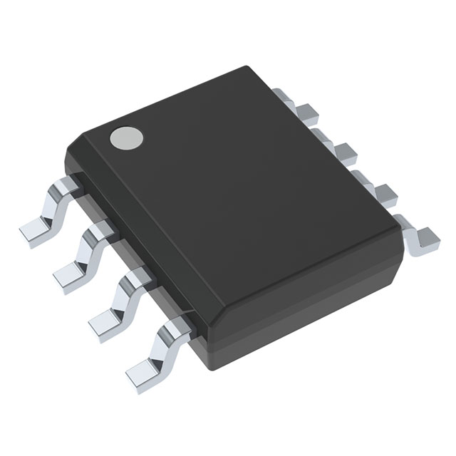
The TLC25M2ACD is a CMOS amplifier integrated circuit manufactured by Texas Instruments, configured as a 2-circuit open drain amplifier in an 8-SOIC surface mount package. This device operates within a supply voltage range of 1.4 V to 16 V and is designed for applications requiring low-power CMOS amplification with open drain output configuration.
The TLC25M2ACD carries a Last Time Buy product status, indicating that Texas Instruments has discontinued this part number. This status necessitates identification of equivalent and substitute components to maintain design continuity and ensure long-term component availability for new designs and production requirements.
Substiute Parts
Key Parameters
| Parameter | Value | Unit |
|---|---|---|
| Amplifier Type | CMOS | — |
| Number of Circuits | 2 | — |
| Output Type | Open Drain | — |
| Slew Rate | 2.9 | V/µs |
| Gain Bandwidth Product | 1.7 | MHz |
| Current - Input Bias | 0.7 | pA |
| Voltage - Input Offset | 900 | µV |
| Current - Supply (x2 Channels) | 285 | µA |
| Voltage - Supply Span (Min) | 1.4 | V |
| Voltage - Supply Span (Max) | 16 | V |
| Operating Temperature | 0 to 70 | °C |
| Package / Case | 8-SOIC (0.154", 3.90mm Width) | — |
| Mounting Type | Surface Mount | — |
| RoHS Status | ROHS3 Compliant | — |
| Moisture Sensitivity Level | 1 (Unlimited) | — |
Substitute Part Grouping Explanation
Substitution of the TLC25M2ACD is determined by compatibility across the following critical parameters:
Package and Mounting Compatibility: All substitute parts must use the 8-SOIC surface mount package with identical 0.154" (3.90mm) width to ensure direct PCB footprint compatibility.
Amplifier Configuration: Substitute parts must be dual-circuit (2-circuit) CMOS amplifiers to maintain functional equivalence in applications requiring two independent amplification channels.
Electrical Operating Range: The supply voltage span must encompass or exceed the original 1.4 V to 16 V range. Parts with minimum supply voltage requirements higher than 1.4 V may not be suitable for applications operating at the lower voltage boundary.
Input Bias Current and Offset Voltage: These parameters define signal fidelity and are critical for precision applications. Substitute parts with comparable or superior specifications (lower input bias current and offset voltage) maintain design performance.
Supply Current Consumption: The 285 µA per dual-channel specification establishes power budget requirements. Substitute parts with significantly higher supply current may impact system power consumption.
Operating Temperature Range: The 0°C to 70°C range defines the commercial operating environment. Substitute parts with extended temperature ranges (such as -40°C to 125°C) provide additional operational flexibility without compromising the specified range.
Slew Rate and Gain Bandwidth Product: These parameters define signal fidelity and frequency response. Substitute parts with equal or superior specifications maintain or improve dynamic performance characteristics.
Parameter Comparison
| Part Number | Manufacturer | Amplifier Type | Number of Circuits | Slew Rate (V/µs) | Gain Bandwidth Product (MHz) | Input Bias Current (pA) | Input Offset Voltage (µV) | Supply Current x2 (µA) | Supply Voltage Min (V) | Supply Voltage Max (V) | Operating Temperature (°C) | Package | Product Status |
|---|---|---|---|---|---|---|---|---|---|---|---|---|---|
| TLC25M2ACD | Texas Instruments | CMOS | 2 | 2.9 | 1.7 | 0.7 | 900 | 285 | 1.4 | 16 | 0 to 70 | 8-SOIC | Last Time Buy |
| TLC27M2ACDR | Texas Instruments | CMOS | 2 | 0.62 | 0.635 | 0.7 | 900 | 285 | 4 | 16 | 0 to 70 | 8-SOIC | Active |
| LM432MA/NOPB | Texas Instruments | General Purpose | 2 | — | 1 | 3000 | 600 | 150 | 2.5 | 16 | -40 to 85 | 8-SOIC | Obsolete |
| TS272ACDT | STMicroelectronics | CMOS | 2 | 5.5 | 3.5 | 1 | 900 | 1000 | 3 | 16 | 0 to 70 | 8-SOIC | Active |
| TS272AIDT | STMicroelectronics | CMOS | 2 | 5.5 | 3.5 | 1 | 900 | 1000 | 3 | 16 | -40 to 125 | 8-SOIC | Active |
| TS272BIDT | STMicroelectronics | CMOS | 2 | 5.5 | 3.5 | 1 | 250 | 1000 | 3 | 16 | -40 to 125 | 8-SOIC | Active |
| TS272CDT | STMicroelectronics | CMOS | 2 | 5.5 | 3.5 | 1 | 1100 | 1000 | 3 | 16 | 0 to 70 | 8-SOIC | Active |
| TS272IDT | STMicroelectronics | CMOS | 2 | 5.5 | 3.5 | 1 | 1100 | 1000 | 3 | 16 | -40 to 125 | 8-SOIC | Active |
| TS27L2ACDT | STMicroelectronics | CMOS | 2 | 0.04 | 0.1 | 1 | 900 | 10 | 3 | 16 | 0 to 70 | 8-SOIC | Active |
| TS27L2AIDT | STMicroelectronics | CMOS | 2 | 0.04 | 0.1 | 1 | 1100 | 10 | 3 | 16 | -40 to 125 | 8-SOIC | Active |
| TS27L2BIDT | STMicroelectronics | CMOS | 2 | 0.04 | 0.1 | 1 | 250 | 10 | 3 | 16 | -40 to 125 | 8-SOIC | Active |
Engineering Selection Recommendations
Primary Recommendation: TLC27M2ACDR
The TLC27M2ACDR is the manufacturer-recommended direct substitute from Texas Instruments. This part maintains identical CMOS amplifier architecture, dual-circuit configuration, and 8-SOIC package footprint. Both devices share the same input bias current specification (0.7 pA) and input offset voltage (900 µV), ensuring signal fidelity equivalent to the original TLC25M2ACD. The TLC27M2ACDR carries Active product status, confirming long-term availability and manufacturing support. Both parts are ROHS3 compliant with MSL 1 rating. The primary electrical difference is the minimum supply voltage requirement of 4 V for the TLC27M2ACDR compared to 1.4 V for the TLC25M2ACD; applications operating below 4 V supply voltage cannot use this substitute.
Secondary Recommendation: TS272 Series (STMicroelectronics)
The TS272 series from STMicroelectronics provides active, widely available alternatives in multiple temperature and packaging variants. The TS272ACDT and TS272CDT variants operate within the 0°C to 70°C temperature range matching the original part, while TS272AIDT and TS272IDT extend operation to -40°C to 125°C. All TS272 variants feature superior slew rate (5.5 V/µs versus 2.9 V/µs) and gain bandwidth product (3.5 MHz versus 1.7 MHz), providing enhanced dynamic performance. The TS272 series requires minimum supply voltage of 3 V, which is compatible with most applications designed for the TLC25M2ACD. Supply current consumption is higher at 1 mA per dual-channel compared to 285 µA, requiring power budget evaluation. All TS272 variants are ROHS3 compliant with MSL 1 rating.
Tertiary Recommendation: TS27L2 Series (STMicroelectronics)
The TS27L2 series offers ultra-low power consumption (10 µA per dual-channel) suitable for battery-powered and energy-constrained applications. This series sacrifices bandwidth (100 kHz gain bandwidth product) and slew rate (0.04 V/µs) compared to the original part, making it suitable only for low-frequency signal processing applications. The TS27L2ACDT and TS27L2AIDT variants maintain 900 µV input offset voltage, while TS27L2BIDT reduces this to 250 µV. Extended temperature variants (TS27L2AIDT and TS27L2BIDT) operate to -40°C to 125°C. All TS27L2 variants require minimum supply voltage of 3 V and are ROHS3 compliant with MSL 1 rating.
Not Recommended: LM432MA/NOPB
The LM432MA/NOPB carries Obsolete product status and should not be selected for new designs. Although this part shares the 8-SOIC package and dual-circuit configuration, it is a general-purpose amplifier rather than a CMOS amplifier, resulting in significantly higher input bias current (3 nA versus 0.7 pA) and lower supply current efficiency (150 µA versus 285 µA). The extended operating temperature range (-40°C to 85°C) and lower minimum supply voltage (2.5 V) do not offset the obsolescence status and inferior input characteristics.
Frequently Asked Questions (FAQ)
Q: Can the TLC27M2ACDR be used as a direct replacement for the TLC25M2ACD in all applications?
A: The TLC27M2ACDR is electrically compatible with the TLC25M2ACD in applications where the supply voltage is 4 V or higher. The TLC25M2ACD operates at supply voltages as low as 1.4 V, while the TLC27M2ACDR requires a minimum of 4 V. Applications operating below 4 V supply voltage cannot use the TLC27M2ACDR without circuit redesign. Both parts share identical input bias current, input offset voltage, and package footprint, ensuring PCB compatibility and signal fidelity for qualifying applications.
Q: What is the difference between the TS272 and TS27L2 series?
A: The TS272 and TS27L2 series differ fundamentally in bandwidth and power consumption. The TS272 series provides 3.5 MHz gain bandwidth product with 1 mA supply current per dual-channel, suitable for general-purpose and moderate-frequency applications. The TS27L2 series provides 100 kHz gain bandwidth product with 10 µA supply current per dual-channel, optimized for ultra-low-power, low-frequency applications. Selection between these series depends on application bandwidth requirements and power budget constraints.
Q: Are all substitute parts ROHS3 compliant?
A: Yes, all substitute parts listed in this reference (TLC27M2ACDR, TS272 series, and TS27L2 series) are ROHS3 compliant with Moisture Sensitivity Level 1 (Unlimited). The original TLC25M2ACD is also ROHS3 compliant with MSL 1. All parts are suitable for applications requiring environmental compliance certification.
Q: What is the significance of the different TS272 variants (ACDT, AIDT, BIDT, CDT, IDT)?
A: The TS272 variants differ in operating temperature range and input offset voltage specification. The "A" suffix indicates 0°C to 70°C operation, while the "I" suffix indicates -40°C to 125°C operation. The "C" and "B" designations specify input offset voltage: "C" variants specify 1.1 mV offset, while "B" variants specify 250 µV offset. The "DT" suffix indicates Cut Tape & Digi-Reel packaging, while "IDT" indicates Tape & Reel packaging. Selection depends on application temperature requirements and offset voltage tolerance.
Q: Can the TS27L2 series be used in applications requiring the 1.7 MHz bandwidth of the TLC25M2ACD?
A: No. The TS27L2 series provides only 100 kHz gain bandwidth product, which is insufficient for applications requiring 1.7 MHz bandwidth. The TS27L2 series is suitable only for low-frequency signal processing applications. For applications requiring bandwidth comparable to the TLC25M2ACD, the TS272 series (3.5 MHz) or TLC27M2ACDR (0.635 MHz) should be selected.
Q: What is the minimum supply voltage requirement for each substitute part?
A: The TLC27M2ACDR requires minimum 4 V supply voltage. The TS272 series (all variants) requires minimum 3 V supply voltage. The TS27L2 series (all variants) requires minimum 3 V supply voltage. Applications operating at the TLC25M2ACD minimum of 1.4 V supply voltage cannot use any of these substitutes without circuit redesign to increase supply voltage.
Q: Are the substitute parts available in the same packaging as the TLC25M2ACD?
A: The TLC25M2ACD is supplied in Tube packaging. The TLC27M2ACDR is supplied in Tape & Reel packaging. The TS272 series is available in both Cut Tape & Digi-Reel and Tape & Reel packaging variants. The TS27L2 series is available in both Tape & Reel and Cut Tape & Digi-Reel packaging variants. All substitute parts use the 8-SOIC (0.154", 3.90mm Width) package, ensuring identical PCB footprint compatibility regardless of packaging format.
Alternative Parts

SJ6012L2TP
Littelfuse Inc.
6 Alternative Parts

JMK107BBJ476MA-RE
Taiyo Yuden
10 Alternative Parts

GMK107BBJ475MA-T
Taiyo Yuden
5 Alternative Parts
SJ6020N2ARP
Littelfuse Inc.
3 Alternative Parts
SJ6025R2ATP
Littelfuse Inc.
4 Alternative Parts

2474-05L
API Delevan Inc.
1 Alternative Parts

4590R-684K
API Delevan Inc.
1 Alternative Parts

CM6560R-334
API Delevan Inc.
1 Alternative Parts

CM6460-104
API Delevan Inc.
1 Alternative Parts

5526-12
API Delevan Inc.
1 Alternative Parts