


Request Quote
(Ships tomorrow)
TLC25L2CP Equivalent & Substitute Parts
Part Overview
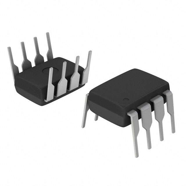
The TLC25L2CP is a CMOS linear amplifier integrated circuit manufactured by Texas Instruments, featuring two independent amplifier circuits in an 8-pin DIP package. This device is classified as Last Time Buy, indicating discontinued production with limited inventory availability. The TLC25L2CP operates across a wide supply voltage range (1.4V to 16V) and is designed for low-power applications requiring minimal input bias current and offset voltage. Due to its Last Time Buy status, identifying equivalent and substitute parts is essential for design continuity and long-term component sourcing.
Substiute Parts
Key Parameters
| Parameter | Value | Unit |
|---|---|---|
| Manufacturer Part Number | TLC25L2CP | — |
| Manufacturer | Texas Instruments | — |
| Category | Linear, Amplifiers | — |
| Amplifier Type | CMOS | — |
| Number of Circuits | 2 | — |
| Output Type | Single-Ended | — |
| Slew Rate | 2.9 | V/µs |
| Gain Bandwidth Product | 110 | kHz |
| Current - Input Bias | 0.7 | pA |
| Voltage - Input Offset | 1.1 | mV |
| Current - Supply | 29 (x2 Channels) | µA |
| Voltage - Supply Span (Min) | 1.4 | V |
| Voltage - Supply Span (Max) | 16 | V |
| Operating Temperature | 0 to 70 | °C |
| Mounting Type | Through Hole | — |
| Package / Case | 8-DIP (0.300", 7.62mm) | — |
| Product Status | Last Time Buy | — |
| RoHS Status | ROHS3 Compliant | — |
Substitute Part Grouping Explanation
Substitution of the TLC25L2CP is determined by the following critical parameters:
Primary Substitution Criteria:
- Number of circuits: Must be 2 independent amplifier circuits
- Amplifier type: CMOS technology preferred for compatibility with low-power specifications
- Supply voltage range: Minimum 1.4V to 16V overlap required
- Input bias current: Must not exceed 0.7 pA (CMOS devices) or 25 nA (general-purpose devices)
- Voltage offset: Must not exceed 1.1 mV
- Gain bandwidth product: 110 kHz minimum
- Operating temperature: 0°C to 70°C minimum coverage
Secondary Considerations:
- Mounting type: Through Hole preferred for direct replacement; Surface Mount requires PCB redesign
- Package compatibility: 8-DIP standard pinout alignment
- Product status: Active status preferred over Last Time Buy
Two substitute parts meet these criteria with different trade-offs:
-
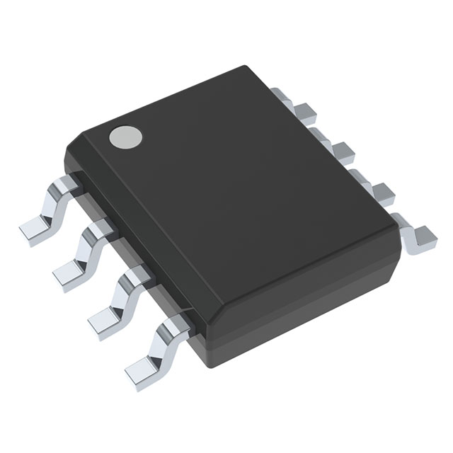
TLC27L2CDR (Texas Instruments): Same manufacturer, same series (LinCMOS™), identical gain bandwidth product, lower supply current, but requires Surface Mount conversion and higher minimum supply voltage (3V vs 1.4V).
-
NJM13404D# (Nisshinbo Micro Devices Inc.): Same package type (8-DIP Through Hole), same number of circuits, Active product status, but uses general-purpose amplifier technology with higher input bias current (25 nA vs 0.7 pA) and significantly higher gain bandwidth product (2 MHz vs 110 kHz).
Parameter Comparison
| Parameter | TLC25L2CP (Main) | TLC27L2CDR (Substitute) | NJM13404D# (Substitute) |
|---|---|---|---|
| Manufacturer | Texas Instruments | Texas Instruments | Nisshinbo Micro Devices Inc. |
| Amplifier Type | CMOS | CMOS | General Purpose |
| Number of Circuits | 2 | 2 | 2 |
| Slew Rate (V/µs) | 2.9 | 0.03 | 1.2 |
| Gain Bandwidth Product (kHz) | 110 | 110 | 2000 |
| Current - Input Bias (pA/nA) | 0.7 pA | 0.6 pA | 25 nA |
| Voltage - Input Offset (mV) | 1.1 | 1.1 | 0.5 |
| Current - Supply (µA/mA) | 29 µA (x2) | 20 µA (x2) | 2 mA |
| Voltage - Supply Span Min (V) | 1.4 | 3 | 2 |
| Voltage - Supply Span Max (V) | 16 | 16 | 14 |
| Operating Temperature (°C) | 0 to 70 | 0 to 70 | -40 to 85 |
| Mounting Type | Through Hole | Surface Mount | Through Hole |
| Package / Case | 8-DIP (0.300", 7.62mm) | 8-SOIC (0.154", 3.90mm) | 8-DIP (0.300", 7.62mm) |
| Product Status | Last Time Buy | Active | Active |
| RoHS Status | ROHS3 Compliant | ROHS3 Compliant | RoHS Compliant |
Engineering Selection Recommendations
For Direct Through-Hole Package Replacement:
Select NJM13404D# when PCB layout cannot be modified and Through-Hole mounting is mandatory. This part maintains identical 8-DIP package geometry and pinout compatibility. The NJM13404D# is Active product status, ensuring long-term availability. However, verify that the application circuit tolerates the higher input bias current (25 nA vs 0.7 pA) and significantly higher gain bandwidth product (2 MHz vs 110 kHz). The extended operating temperature range (-40°C to 85°C) provides additional margin beyond the TLC25L2CP specification.
For Surface Mount Conversion:
Select TLC27L2CDR when PCB redesign is feasible and Surface Mount technology is acceptable. This part is from the same manufacturer and LinCMOS™ series, ensuring closest electrical compatibility. The TLC27L2CDR maintains identical gain bandwidth product (110 kHz) and input offset voltage (1.1 mV), with improved supply current efficiency (20 µA vs 29 µA per channel). The minimum supply voltage requirement increases to 3V; verify that the application power supply meets this threshold. Active product status and high inventory (105,200 pcs) support long-term design continuity.
Compliance Verification:
Both substitute parts maintain ROHS3 compliance and REACH Unaffected status, matching the original TLC25L2CP regulatory requirements. ECCN and HTSUS classifications remain consistent across all three parts.
Frequently Asked Questions (FAQ)
Q: Can NJM13404D# directly replace TLC25L2CP without circuit modification?
A: NJM13404D# maintains identical 8-DIP Through-Hole package pinout and can be inserted into existing sockets without PCB modification. However, circuit performance will differ due to higher input bias current (25 nA vs 0.7 pA) and higher gain bandwidth product (2 MHz vs 110 kHz). Applications sensitive to input bias current or requiring precise frequency response must be re-evaluated.
Q: Why does TLC27L2CDR have lower slew rate (0.03 V/µs vs 2.9 V/µs)?
A: The TLC27L2CDR is optimized for ultra-low power consumption in Surface Mount applications. The reduced slew rate reflects different internal circuit design. Verify that the application does not require fast transient response or high-frequency signal handling.
Q: What is the impact of TLC27L2CDR's 3V minimum supply voltage?
A: The TLC25L2CP operates down to 1.4V, while TLC27L2CDR requires minimum 3V. Applications powered by single-cell batteries or ultra-low voltage supplies cannot use TLC27L2CDR. Confirm that the system power supply provides at least 3V before selecting this substitute.
Q: Is pinout identical between TLC25L2CP and NJM13404D#?
A: Both parts use standard 8-DIP package with identical pin assignments for dual-amplifier configuration. Direct socket substitution is possible without rewiring.
Q: Can TLC27L2CDR be used in existing Through-Hole designs?
A: No. TLC27L2CDR uses 8-SOIC Surface Mount package (0.154" width) versus 8-DIP Through-Hole package (0.300" width). PCB redesign and component placement modification are required.
Q: Which substitute offers the best long-term availability?
A: TLC27L2CDR has highest inventory (105,200 pcs) and Active product status. NJM13404D# has lower inventory (776 pcs) but also Active status. Both are superior to TLC25L2CP Last Time Buy status.
Q: Are there temperature range differences to consider?
A: TLC25L2CP and TLC27L2CDR both specify 0°C to 70°C. NJM13404D# extends to -40°C to 85°C, providing wider operating margin for industrial or automotive applications.
Alternative Parts

SJ6012L2TP
Littelfuse Inc.
6 Alternative Parts

JMK107BBJ476MA-RE
Taiyo Yuden
10 Alternative Parts

GMK107BBJ475MA-T
Taiyo Yuden
5 Alternative Parts
SJ6020N2ARP
Littelfuse Inc.
3 Alternative Parts
SJ6025R2ATP
Littelfuse Inc.
4 Alternative Parts

2474-05L
API Delevan Inc.
1 Alternative Parts

4590R-684K
API Delevan Inc.
1 Alternative Parts

CM6560R-334
API Delevan Inc.
1 Alternative Parts

CM6460-104
API Delevan Inc.
1 Alternative Parts

5526-12
API Delevan Inc.
1 Alternative Parts