


Request Quote
(Ships tomorrow)
TLC082CDR Equivalent & Substitute Parts
Part Overview
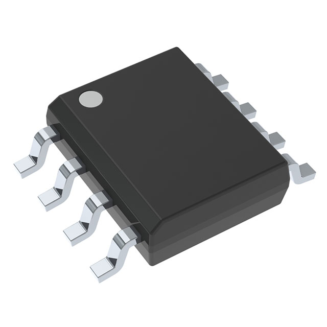
The TLC082CDR is a general purpose operational amplifier manufactured by Texas Instruments, configured as a dual-channel (2 circuit) device in an 8-SOIC surface mount package. This component is classified as Active product status with full RoHS3 compliance and unlimited moisture sensitivity rating (MSL 1).
The TLC082CDR serves applications requiring low-power, general-purpose amplification with moderate bandwidth and slew rate characteristics. Substitute parts become necessary when the original component experiences supply chain constraints, extended lead times, or when design requirements permit operation within broader electrical parameter ranges. Alternative devices must maintain functional equivalence across critical parameters including circuit count, package compatibility, supply voltage range, and amplifier type classification.
Substiute Parts
Key Parameters
| Parameter | Value | Unit |
|---|---|---|
| Amplifier Type | General Purpose | — |
| Number of Circuits | 2 | — |
| Slew Rate | 19 | V/µs |
| Gain Bandwidth Product | 10 | MHz |
| Current - Input Bias | 3 | pA |
| Voltage - Input Offset | 390 | µV |
| Current - Supply | 1.9 (x2 Channels) | mA |
| Current - Output / Channel | 57 | mA |
| Voltage - Supply Span (Min) | 4.5 | V |
| Voltage - Supply Span (Max) | 16 | V |
| Operating Temperature | 0 to 70 | °C |
| Mounting Type | Surface Mount | — |
| Package / Case | 8-SOIC (0.154", 3.90mm Width) | — |
| RoHS Status | ROHS3 Compliant | — |
| Product Status | Active | — |
Substitute Part Grouping Explanation
Substitution eligibility for the TLC082CDR is determined by strict alignment with the following critical parameters:
Primary Substitution Criteria:
- Amplifier Type: General Purpose (required match)
- Number of Circuits: 2 (required match)
- Mounting Type: Surface Mount (required match)
- Package Type: 8-SOIC or 8-SOP (compatible package families)
- RoHS3 Compliance: Required
- Product Status: Active preferred; Obsolete acceptable only with documented inventory
Secondary Compatibility Parameters:
- Voltage Supply Span: Substitute minimum must be ≤4.5V; substitute maximum must be ≥16V
- Gain Bandwidth Product: Substitute minimum 10 MHz acceptable
- Current Output per Channel: Substitute must support ≥57 mA
- Operating Temperature: Substitute range must encompass or exceed 0°C to 70°C
Acceptable Variations:
- Slew Rate: Higher values acceptable (19 V/µs baseline)
- Input Bias Current: Higher values acceptable (3 pA baseline)
- Input Offset Voltage: Variations acceptable within application tolerance
- Supply Current: Variations acceptable if within system power budget
The following parts meet substitution criteria based on these parameters.
Parameter Comparison
| Parameter | TLC082CDR (Main) | LM4565F-GE2 | MC33078DR2G | SC2904VDR2G |
|---|---|---|---|---|
| Manufacturer | Texas Instruments | Rohm Semiconductor | onsemi | onsemi |
| Amplifier Type | General Purpose | General Purpose | General Purpose | General Purpose |
| Number of Circuits | 2 | 2 | 2 | 2 |
| Slew Rate (V/µs) | 19 | 5 | 7 | — |
| Gain Bandwidth Product (MHz) | 10 | 10 | 16 | — |
| Current - Input Bias (pA/nA) | 3 pA | 70 nA | 300 nA | 45 nA |
| Voltage - Input Offset (µV/mV) | 390 µV | 500 µV | 150 µV | 2 mV |
| Current - Supply (mA) | 1.9 | 4.5 | 4.1 | — |
| Current - Output / Channel (mA) | 57 | 160 | 37 | 40 |
| Voltage - Supply Span Min (V) | 4.5 | 4 | 10 | 3 |
| Voltage - Supply Span Max (V) | 16 | 36 | 36 | 26 |
| Operating Temperature (°C) | 0 to 70 | -40 to 85 | -40 to 85 | -40 to 85 |
| Package / Case | 8-SOIC (0.154", 3.90mm) | 8-SOP (0.173", 4.40mm) | 8-SOIC (0.154", 3.90mm) | 8-SOIC (0.154", 3.90mm) |
| Product Status | Active | Active | Active | Obsolete |
| RoHS Status | ROHS3 Compliant | ROHS3 Compliant | ROHS3 Compliant | ROHS3 Compliant |
| Inventory (Pcs) | 20817 | 2353 | 60100 | 698 |
Engineering Selection Recommendations
LM4565F-GE2 (Rohm Semiconductor)
The LM4565F-GE2 qualifies as a substitute based on matching amplifier type, circuit count, and RoHS3 compliance. This part operates within an extended supply voltage range (4V to 36V), accommodating the TLC082CDR minimum requirement of 4.5V. The 8-SOP package (0.173" width) differs from the TLC082CDR 8-SOIC package (0.154" width); PCB layout verification is required for footprint compatibility. Active product status ensures ongoing availability. The LM4565F-GE2 exhibits lower slew rate (5 V/µs versus 19 V/µs) and higher supply current (4.5 mA versus 1.9 mA), requiring evaluation against application bandwidth and power consumption constraints.
MC33078DR2G (onsemi)
The MC33078DR2G meets substitution criteria with matching amplifier type, dual-circuit configuration, and identical 8-SOIC package footprint (0.154", 3.90mm width). Active product status and RoHS3 compliance are confirmed. Supply voltage range (10V to 36V) exceeds the TLC082CDR minimum of 4.5V; applications requiring operation below 10V cannot use this substitute. The MC33078DR2G provides higher gain bandwidth product (16 MHz versus 10 MHz) and superior input offset voltage specification (150 µV versus 390 µV). Output current per channel (37 mA) falls below the TLC082CDR specification (57 mA); applications requiring full 57 mA output current must verify MC33078DR2G capability. Inventory availability (60100 pcs) is substantial.
SC2904VDR2G (onsemi)
The SC2904VDR2G matches package type (8-SOIC, 0.154", 3.90mm width) and circuit configuration (dual general-purpose amplifier). RoHS3 compliance is confirmed. However, this part carries Obsolete product status, indicating discontinued manufacturing and limited future availability (current inventory: 698 pcs). Supply voltage range (3V to 26V) accommodates the TLC082CDR specification. Multiple electrical parameters lack specification data (slew rate, supply current), limiting comprehensive compatibility assessment. Selection of SC2904VDR2G is not recommended for new designs due to obsolete status and incomplete technical documentation.
Frequently Asked Questions (FAQ)
Q: Can the LM4565F-GE2 be used as a direct replacement for the TLC082CDR on existing PCBs?
A: The LM4565F-GE2 uses an 8-SOP package (0.173" width) while the TLC082CDR uses 8-SOIC (0.154" width). Although both are 8-pin surface mount packages, the footprint dimensions differ. PCB layout verification is required to confirm pad spacing and trace routing compatibility. Direct board-level substitution without layout modification is not guaranteed.
Q: What is the primary limitation of the MC33078DR2G as a substitute?
A: The MC33078DR2G minimum supply voltage is 10V, whereas the TLC082CDR operates from 4.5V minimum. Applications requiring operation below 10V supply voltage cannot use the MC33078DR2G. Additionally, output current per channel (37 mA) is lower than the TLC082CDR specification (57 mA); high-current output applications must verify compatibility.
Q: Why is the SC2904VDR2G listed if it is obsolete?
A: The SC2904VDR2G is included for reference purposes only, representing a historical substitute option. Obsolete product status indicates manufacturing discontinuation and severely limited inventory (698 pcs). This part is not recommended for new designs or long-term production applications. Selection should prioritize Active status parts (LM4565F-GE2 or MC33078DR2G).
Q: Are all substitute parts RoHS3 compliant?
A: Yes. The TLC082CDR and all listed substitute parts (LM4565F-GE2, MC33078DR2G, SC2904VDR2G) carry RoHS3 Compliant certification. All parts are also REACH Unaffected and classified under ECCN EAR99 with HTSUS code 8542.33.0001.
Q: Which substitute offers the best overall compatibility?
A: The MC33078DR2G provides the closest electrical and mechanical compatibility: identical 8-SOIC package footprint, Active product status, higher gain bandwidth product (16 MHz), and superior input offset voltage (150 µV). The primary constraint is minimum supply voltage (10V). The LM4565F-GE2 offers lower minimum supply voltage (4V) but requires PCB footprint verification due to package width difference (0.173" versus 0.154").
Q: Can supply current differences affect circuit performance?
A: Supply current differences (TLC082CDR: 1.9 mA; LM4565F-GE2: 4.5 mA; MC33078DR2G: 4.1 mA) impact total system power consumption and thermal dissipation. Applications with strict power budgets or thermal constraints must account for higher supply current in substitute parts. This does not affect functional performance but influences system-level power management.
Q: What parameters should be verified before finalizing a substitution?
A: Verify the following before substitution: (1) Supply voltage range compatibility with application requirements; (2) Package footprint compatibility with PCB layout; (3) Output current capability against load requirements; (4) Slew rate and bandwidth adequacy for signal processing; (5) Operating temperature range coverage; (6) Input offset voltage and bias current tolerance for precision applications.
Alternative Parts

SJ6012L2TP
Littelfuse Inc.
6 Alternative Parts

JMK107BBJ476MA-RE
Taiyo Yuden
10 Alternative Parts

GMK107BBJ475MA-T
Taiyo Yuden
5 Alternative Parts
SJ6020N2ARP
Littelfuse Inc.
3 Alternative Parts
SJ6025R2ATP
Littelfuse Inc.
4 Alternative Parts

2474-05L
API Delevan Inc.
1 Alternative Parts

4590R-684K
API Delevan Inc.
1 Alternative Parts

CM6560R-334
API Delevan Inc.
1 Alternative Parts

CM6460-104
API Delevan Inc.
1 Alternative Parts

5526-12
API Delevan Inc.
1 Alternative Parts