


Request Quote
(Ships tomorrow)
TL074ACD Equivalent & Substitute Parts
Part Overview
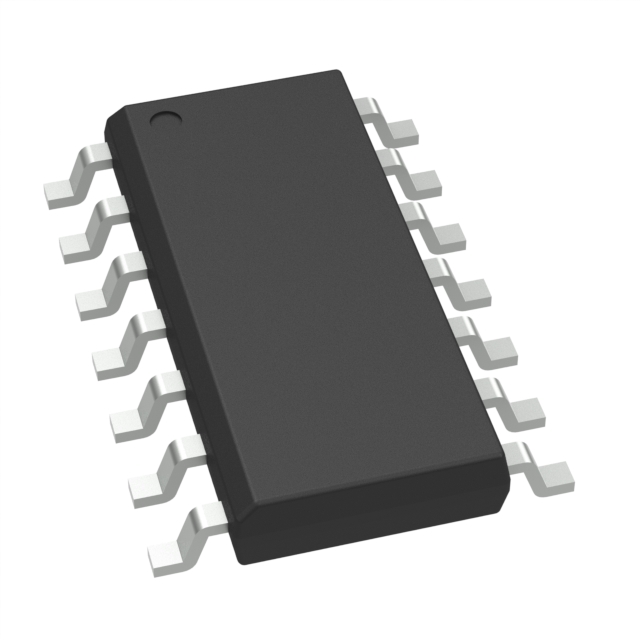
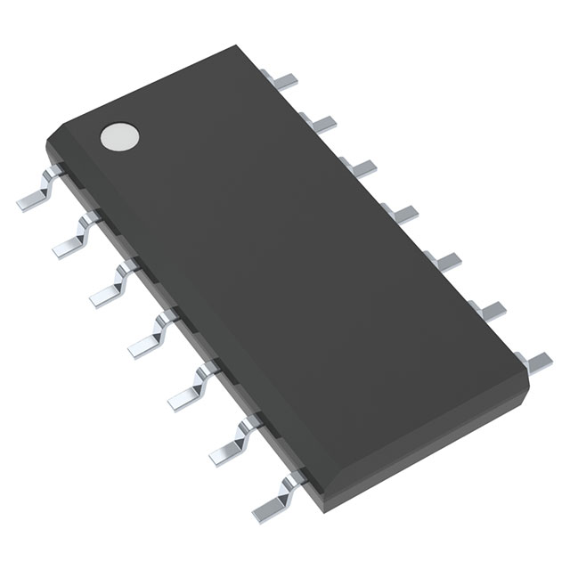
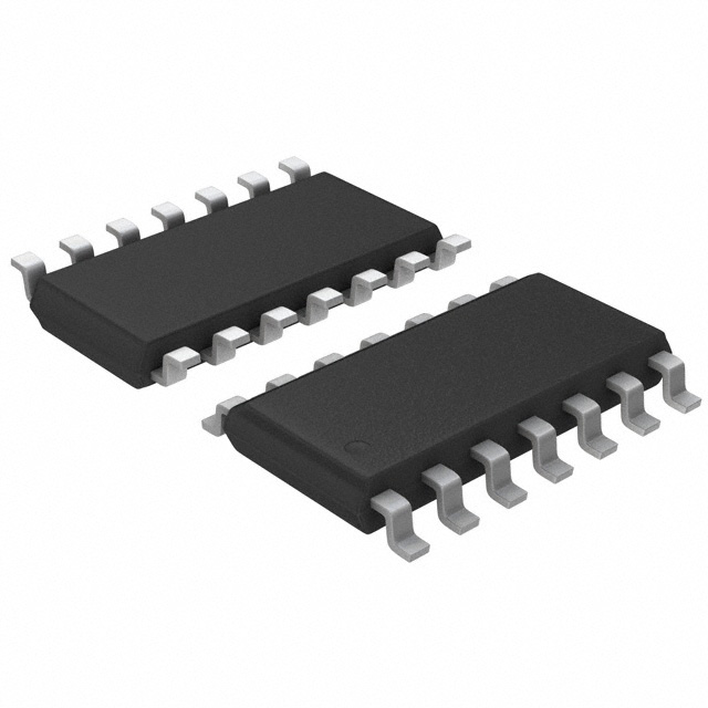
The TL074ACD is a J-FET input operational amplifier integrated circuit manufactured by STMicroelectronics, configured as a 4-circuit device in a 14-SOIC surface mount package. This component is classified as obsolete, though 3930 units remain in stock as new original inventory. The TL074ACD operates across a wide supply voltage range of 6V to 36V and is suitable for applications requiring low input bias current and moderate bandwidth characteristics typical of J-FET amplifier designs.
Due to the obsolete product status of the TL074ACD, identification of equivalent and substitute parts is necessary for design continuity, long-term availability assurance, and potential performance optimization in new production runs or redesign initiatives.
Substiute Parts
Key Parameters
| Parameter | Value | Unit |
|---|---|---|
| Amplifier Type | J-FET | — |
| Number of Circuits | 4 | — |
| Slew Rate | 13 | V/µs |
| Gain Bandwidth Product | 3 | MHz |
| Current - Input Bias | 20 | pA |
| Voltage - Input Offset | 3 | mV |
| Current - Supply (per 4 Channels) | 1.4 | mA |
| Current - Output / Channel | 40 | mA |
| Voltage - Supply Span (Min) | 6 | V |
| Voltage - Supply Span (Max) | 36 | V |
| Operating Temperature Range | 0 to 70 | °C |
| Package / Case | 14-SOIC (0.154", 3.90mm Width) | — |
| Mounting Type | Surface Mount | — |
| RoHS Status | ROHS3 Compliant | — |
| Moisture Sensitivity Level | 1 (Unlimited) | — |
Substitute Part Grouping Explanation
Substitute parts for the TL074ACD are evaluated based on strict electrical and mechanical compatibility criteria. The primary substitution parameters are:
Critical Matching Parameters:
- Amplifier Type: J-FET configuration
- Number of Circuits: 4-circuit configuration
- Package / Case: 14-SOIC form factor (0.154", 3.90mm Width)
- Mounting Type: Surface Mount
- Supply Voltage Range: Minimum 6V to Maximum 36V overlap
Performance Parameters (Secondary Consideration):
- Slew Rate: 13 V/µs baseline
- Gain Bandwidth Product: 3 MHz baseline
- Input Bias Current: 20 pA baseline
- Input Offset Voltage: 3 mV baseline
- Output Current per Channel: 40 mA baseline
- Supply Current: 1.4 mA per 4 channels baseline
Substitute parts are grouped into two categories:
Category A - J-FET Amplifiers (Direct Functional Equivalents): Parts maintaining J-FET amplifier topology with 4 circuits in 14-SOIC packaging. These include AD8513ARZ, AD8513ARZ-REEL, AD8513ARZ-REEL7, AD8684ARZ, AD8684ARZ-REEL, AD8684ARZ-REEL7, and ADA4000-4ARZ. These substitutes preserve the core J-FET input characteristics while offering active product status and enhanced performance specifications.
Category B - General Purpose Amplifiers (Functional Alternatives): Parts including AD8674ARZ, AD8674ARZ-REEL, and AD8674ARZ-REEL7 represent general purpose amplifier topology with 4 circuits in 14-SOIC packaging. These differ in amplifier type but maintain package compatibility and 4-circuit configuration.
Parameter Comparison
| Parameter | TL074ACD | AD8513ARZ | AD8513ARZ-REEL | AD8513ARZ-REEL7 | AD8684ARZ | AD8684ARZ-REEL | AD8684ARZ-REEL7 | ADA4000-4ARZ | AD8674ARZ | AD8674ARZ-REEL | AD8674ARZ-REEL7 |
|---|---|---|---|---|---|---|---|---|---|---|---|
| Manufacturer | STMicroelectronics | Analog Devices Inc. | Analog Devices Inc. | Analog Devices Inc. | Analog Devices Inc. | Analog Devices Inc. | Analog Devices Inc. | Analog Devices Inc. | Analog Devices Inc. | Analog Devices Inc. | Analog Devices Inc. |
| Amplifier Type | J-FET | J-FET | J-FET | J-FET | J-FET | J-FET | J-FET | J-FET | General Purpose | General Purpose | General Purpose |
| Number of Circuits | 4 | 4 | 4 | 4 | 4 | 4 | 4 | 4 | 4 | 4 | 4 |
| Slew Rate (V/µs) | 13 | 20 | 20 | 20 | 9 | 9 | 9 | 20 | 4 | 4 | 4 |
| Gain Bandwidth Product (MHz) | 3 | 8 | 8 | 8 | 3.5 | 3.5 | 3.5 | 5 | 10 | 10 | 10 |
| Current - Input Bias (pA) | 20 | 25 | 25 | 25 | 6 | 6 | 6 | 5 | 3000 | 3000 | 3000 |
| Voltage - Input Offset (mV) | 3 | 0.1 | 0.1 | 0.1 | 0.35 | 0.35 | 0.35 | 0.2 | 0.02 | 0.02 | 0.02 |
| Current - Supply per 4 Channels (mA) | 1.4 | 2.2 | 2.2 | 2.2 | 0.21 | 0.21 | 0.21 | 1.35 | 3 | 3 | 3 |
| Current - Output / Channel (mA) | 40 | 70 | 70 | 70 | 12 | 12 | 12 | 28 | 20 | 20 | 20 |
| Voltage - Supply Span Min (V) | 6 | 10 | 10 | 10 | 9 | 9 | 9 | 8 | 10 | 10 | 10 |
| Voltage - Supply Span Max (V) | 36 | 30 | 30 | 30 | 36 | 36 | 36 | 36 | 36 | 36 | 36 |
| Operating Temperature Range (°C) | 0 to 70 | -40 to 125 | -40 to 125 | -40 to 125 | -40 to 85 | -40 to 85 | -40 to 85 | -40 to 125 | -40 to 85 | -40 to 85 | -40 to 85 |
| Package / Case | 14-SOIC (0.154", 3.90mm Width) | 14-SOIC (0.154", 3.90mm Width) | 14-SOIC (0.154", 3.90mm Width) | 14-SOIC (0.154", 3.90mm Width) | 14-SOIC (0.154", 3.90mm Width) | 14-SOIC (0.154", 3.90mm Width) | 14-SOIC (0.154", 3.90mm Width) | 14-SOIC (0.154", 3.90mm Width) | 14-SOIC (0.154", 3.90mm Width) | 14-SOIC (0.154", 3.90mm Width) | 14-SOIC (0.154", 3.90mm Width) |
| Mounting Type | Surface Mount | Surface Mount | Surface Mount | Surface Mount | Surface Mount | Surface Mount | Surface Mount | Surface Mount | Surface Mount | Surface Mount | Surface Mount |
| Product Status | Obsolete | Active | Active | Active | Active | Active | Active | Active | Active | Active | Active |
| RoHS Status | ROHS3 Compliant | ROHS3 Compliant | ROHS3 Compliant | ROHS3 Compliant | ROHS3 Compliant | ROHS3 Compliant | ROHS3 Compliant | ROHS3 Compliant | ROHS3 Compliant | ROHS3 Compliant | ROHS3 Compliant |
| Moisture Sensitivity Level | 1 (Unlimited) | 1 (Unlimited) | 1 (Unlimited) | 1 (Unlimited) | 1 (Unlimited) | 1 (Unlimited) | 1 (Unlimited) | 1 (Unlimited) | 1 (Unlimited) | 1 (Unlimited) | 1 (Unlimited) |
Engineering Selection Recommendations
All substitute parts listed maintain ROHS3 compliance and MSL Level 1 (Unlimited) moisture sensitivity rating, consistent with the TL074ACD. All substitute parts are manufactured by Analog Devices Inc. and carry active product status, ensuring long-term availability and supply chain continuity.
For J-FET Amplifier Applications Requiring Direct Topology Preservation:
The AD8513ARZ, AD8513ARZ-REEL, and AD8513ARZ-REEL7 series provide J-FET amplifier configuration with enhanced performance characteristics. These parts operate across a 10V to 30V supply range, which overlaps the TL074ACD range above 10V. The AD8513 series exhibits higher slew rate (20 V/µs versus 13 V/µs) and greater gain bandwidth product (8 MHz versus 3 MHz), with marginally higher input bias current (25 pA versus 20 pA) and significantly lower input offset voltage (100 µV versus 3 mV). Output current capability is increased to 70 mA per channel. Operating temperature range extends to -40°C to 125°C.
The AD8684ARZ, AD8684ARZ-REEL, and AD8684ARZ-REEL7 series maintain J-FET topology with supply range of 9V to 36V, fully encompassing the TL074ACD range. The AD8684 series exhibits lower slew rate (9 V/µs versus 13 V/µs) and comparable gain bandwidth product (3.5 MHz versus 3 MHz). Input bias current is significantly reduced (6 pA versus 20 pA), and supply current consumption is substantially lower (210 µA per 4 channels versus 1.4 mA). Output current per channel is reduced to 12 mA. Operating temperature range extends to -40°C to 85°C.
The ADA4000-4ARZ provides J-FET amplifier configuration with supply range of 8V to 36V. This part exhibits higher slew rate (20 V/µs versus 13 V/µs), higher gain bandwidth product (5 MHz versus 3 MHz), and lower input bias current (5 pA versus 20 pA). Input offset voltage is reduced to 200 µV. Output current per channel is 28 mA. Operating temperature range extends to -40°C to 125°C.
For General Purpose Amplifier Applications:
The AD8674ARZ, AD8674ARZ-REEL, and AD8674ARZ-REEL7 series provide general purpose amplifier configuration with supply range of 10V to 36V. These parts differ in amplifier type from the TL074ACD but maintain 4-circuit configuration in 14-SOIC packaging. The AD8674 series exhibits lower slew rate (4 V/µs versus 13 V/µs) and higher gain bandwidth product (10 MHz versus 3 MHz). Input bias current is substantially higher (3 nA versus 20 pA), reflecting general purpose rather than J-FET topology. Input offset voltage is significantly lower (20 µV versus 3 mV). Output current per channel is 20 mA. Operating temperature range extends to -40°C to 85°C.
Packaging Considerations:
All substitute parts are available in 14-SOIC surface mount package with identical footprint dimensions (0.154", 3.90mm Width). Packaging variants include Tube (standard), Tape & Reel (TR), and Cut Tape with Digi-Reel (CT). Selection between packaging variants depends on production volume and assembly process requirements.
Frequently Asked Questions (FAQ)
Q: Can the AD8513ARZ directly replace the TL074ACD in all applications?
A: The AD8513ARZ maintains J-FET amplifier topology and 4-circuit configuration in identical 14-SOIC packaging. However, the supply voltage minimum is 10V versus 6V for the TL074ACD. Applications operating below 10V supply voltage require alternative selection. The AD8513ARZ exhibits enhanced performance with higher slew rate and gain bandwidth product, lower input offset voltage, and extended operating temperature range. Circuit validation is necessary to confirm compatibility with specific application requirements.
Q: What is the primary difference between the AD8684ARZ and AD8513ARZ?
A: Both parts maintain J-FET amplifier topology in 14-SOIC packaging. The AD8684ARZ operates across a wider supply range (9V to 36V) compared to the AD8513ARZ (10V to 30V). The AD8684ARZ exhibits lower slew rate (9 V/µs versus 20 V/µs) and comparable gain bandwidth product (3.5 MHz versus 8 MHz). The AD8684ARZ provides significantly lower supply current consumption (210 µA per 4 channels versus 2.2 mA) and lower input bias current (6 pA versus 25 pA), making it suitable for low-power applications. Output current per channel is reduced to 12 mA versus 70 mA.
Q: Why would the AD8674 series be selected over J-FET alternatives?
A: The AD8674 series represents general purpose amplifier topology rather than J-FET configuration. Selection of the AD8674 series is appropriate when J-FET input characteristics are not required and general purpose amplifier performance is acceptable. The AD8674 series offers higher gain bandwidth product (10 MHz versus 3 MHz for TL074ACD) and significantly lower input offset voltage (20 µV versus 3 mV). However, input bias current is substantially higher (3 nA versus 20 pA), which may be unsuitable for high-impedance signal sources. Supply current consumption is higher (3 mA per 4 channels versus 1.4 mA).
Q: Are all substitute parts RoHS3 compliant?
A: All substitute parts listed are ROHS3 compliant and carry MSL Level 1 (Unlimited) moisture sensitivity rating, consistent with the TL074ACD. All parts are manufactured by Analog Devices Inc. and carry active product status, ensuring regulatory compliance and long-term availability.
Q: What packaging options are available for substitute parts?
A: Substitute parts are available in three packaging formats: Tube (standard packaging for lower volumes), Tape & Reel (TR) for automated assembly, and Cut Tape with Digi-Reel (CT) for mixed-volume production. All packaging variants contain identical die and electrical specifications. Selection depends on production volume, assembly equipment compatibility, and inventory management requirements.
Q: Can the ADA4000-4ARZ operate at the TL074ACD minimum supply voltage of 6V?
A: No. The ADA4000-4ARZ requires a minimum supply voltage of 8V, which is higher than the TL074ACD minimum of 6V. Applications requiring operation at 6V or 7V supply voltage must select alternative parts such as the AD8684ARZ (9V minimum) or remain with the TL074ACD. The ADA4000-4ARZ is suitable for applications with supply voltages of 8V and above.
Q: How does input bias current affect circuit design?
A: Input bias current determines the magnitude of current flowing into the amplifier input terminals. The TL074ACD exhibits 20 pA input bias current, characteristic of J-FET input amplifiers. The AD8684ARZ provides lower input bias current (6 pA), while the AD8674 series exhibits significantly higher input bias current (3 nA) due to general purpose amplifier topology. Lower input bias current is advantageous for high-impedance signal sources and transimpedance amplifier configurations. Higher input bias current may require input bias current compensation networks in sensitive applications.
Q: What is the significance of slew rate in amplifier selection?
A: Slew rate defines the maximum rate of change of output voltage per unit time, expressed in V/µs. The TL074ACD exhibits 13 V/µs slew rate. Higher slew rate (AD8513ARZ at 20 V/µs, ADA4000-4ARZ at 20 V/µs) enables faster signal reproduction and reduced distortion in high-frequency applications. Lower slew rate (AD8684ARZ at 9 V/µs, AD8674 series at 4 V/µs) is acceptable for lower-frequency applications and reduces power consumption. Slew rate limitations can cause distortion if exceeded in specific circuit configurations.
Q: Does the operating temperature range affect part selection?
A: The TL074ACD operates across 0°C to 70°C. Most substitute parts extend the operating temperature range to -40°C to 85°C or -40°C to 125°C. Extended temperature range provides design flexibility for applications requiring operation outside the TL074ACD range. However, extended temperature range does not affect performance within the TL074ACD operating window. Selection based on temperature range is necessary only when applications require operation outside 0°C to 70°C.
Alternative Parts

SJ6012L2TP
Littelfuse Inc.
6 Alternative Parts

JMK107BBJ476MA-RE
Taiyo Yuden
10 Alternative Parts

GMK107BBJ475MA-T
Taiyo Yuden
5 Alternative Parts
SJ6020N2ARP
Littelfuse Inc.
3 Alternative Parts
SJ6025R2ATP
Littelfuse Inc.
4 Alternative Parts

2474-05L
API Delevan Inc.
1 Alternative Parts

4590R-684K
API Delevan Inc.
1 Alternative Parts

CM6560R-334
API Delevan Inc.
1 Alternative Parts

CM6460-104
API Delevan Inc.
1 Alternative Parts

5526-12
API Delevan Inc.
1 Alternative Parts