


Request Quote
(Ships tomorrow)
TIP34C Equivalent & Substitute Parts
Part Overview
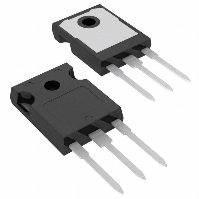
The TIP34C is a PNP bipolar junction transistor manufactured by STMicroelectronics, rated for 100 V collector-emitter breakdown voltage and 10 A maximum collector current in a TO-247-3 through-hole package. This device is classified as obsolete, making identification of functionally equivalent alternatives necessary for ongoing design support and procurement continuity. The TIP34C delivers 80 W maximum power dissipation with a 3 MHz transition frequency, suitable for general-purpose switching and amplification applications requiring moderate voltage and current handling.
Substiute Parts
Key Parameters
| Parameter | Value | Unit |
|---|---|---|
| Transistor Type | PNP | — |
| Current - Collector (Ic) (Max) | 10 | A |
| Voltage - Collector Emitter Breakdown (Max) | 100 | V |
| Power - Max | 80 | W |
| Frequency - Transition | 3 | MHz |
| DC Current Gain (hFE) (Min) @ Ic, Vce | 20 @ 3A, 4V | — |
| Vce Saturation (Max) @ Ib, Ic | 4V @ 2.5A, 10A | — |
| Package / Case | TO-247-3 | — |
| Mounting Type | Through Hole | — |
| Operating Temperature (Max) | 150 | °C (TJ) |
Substitute Part Grouping Explanation
Substitution of the obsolete TIP34C requires identification of PNP transistors sharing the same TO-247-3 through-hole package and compatible electrical characteristics. The primary substitution criteria are:
- Transistor Type: Must be PNP configuration
- Package Compatibility: TO-247-3 through-hole mounting
- Voltage Rating: Collector-emitter breakdown voltage must equal or exceed application requirements
- Current Capability: Collector current rating must support circuit demands
- Power Dissipation: Maximum power rating must accommodate thermal requirements
- DC Current Gain: Minimum hFE must satisfy biasing and switching performance
- Saturation Characteristics: Vce(sat) must meet circuit specifications
The TIP2955G qualifies as a substitute based on matching package type, PNP configuration, and compatible electrical parameters within the allowed operating envelope. While the TIP2955G exhibits different absolute ratings (60 V breakdown versus 100 V, 15 A versus 10 A collector current), these differences establish a substitution relationship where the TIP2955G operates within a subset of the TIP34C's design space for applications not requiring the full 100 V rating.
Parameter Comparison
| Parameter | TIP34C (Main Part) | TIP2955G (Substitute) | Unit |
|---|---|---|---|
| Manufacturer | STMicroelectronics | onsemi | — |
| Product Status | Obsolete | Active | — |
| Transistor Type | PNP | PNP | — |
| Current - Collector (Ic) (Max) | 10 | 15 | A |
| Voltage - Collector Emitter Breakdown (Max) | 100 | 60 | V |
| Vce Saturation (Max) @ Ib, Ic | 4V @ 2.5A, 10A | 3V @ 3.3A, 10A | — |
| Current - Collector Cutoff (Max) | 700 | 700 | µA |
| DC Current Gain (hFE) (Min) @ Ic, Vce | 20 @ 3A, 4V | 20 @ 4A, 4V | — |
| Power - Max | 80 | 90 | W |
| Frequency - Transition | 3 | 2.5 | MHz |
| Operating Temperature (Max) | 150 | 150 | °C (TJ) |
| Package / Case | TO-247-3 | TO-247-3 | — |
| Mounting Type | Through Hole | Through Hole | — |
| RoHS Status | ROHS3 Compliant | ROHS3 Compliant | — |
| REACH Status | REACH Unaffected | REACH Unaffected | — |
Engineering Selection Recommendations
The TIP2955G is an active-status substitute for the obsolete TIP34C. Both devices maintain ROHS3 compliance and REACH unaffected status, ensuring regulatory alignment for new designs and legacy system support.
Selection Criteria:
-
For applications operating at or below 60 V: The TIP2955G provides direct substitution with superior current handling (15 A versus 10 A) and improved saturation characteristics (3 V versus 4 V at 10 A collector current).
-
For applications requiring 100 V operation: The TIP34C's higher voltage rating cannot be replaced by the TIP2955G. Alternative PNP transistors with 100 V or greater breakdown voltage in TO-247-3 packaging must be evaluated.
-
For thermal management: The TIP2955G offers 10 W additional power dissipation capacity (90 W versus 80 W), providing design margin in power-limited applications.
-
For frequency-sensitive circuits: The TIP34C's 3 MHz transition frequency exceeds the TIP2955G's 2.5 MHz rating. Applications requiring higher switching speeds must account for this 0.5 MHz reduction.
The TIP2955G's active product status ensures long-term availability and manufacturing support, eliminating obsolescence risk associated with the TIP34C.
Frequently Asked Questions (FAQ)
Q: Can the TIP2955G replace the TIP34C in all applications?
A: No. The TIP2955G operates at a maximum collector-emitter breakdown voltage of 60 V, compared to the TIP34C's 100 V rating. Substitution is valid only for circuits operating at 60 V or below. Applications requiring the full 100 V rating require alternative components.
Q: What are the package compatibility considerations?
A: Both the TIP34C and TIP2955G use the TO-247-3 through-hole package with identical pin configuration and mounting footprint. No PCB layout modifications are required for mechanical substitution.
Q: How do the saturation characteristics compare?
A: At 10 A collector current, the TIP2955G exhibits 3 V saturation voltage versus the TIP34C's 4 V. This 1 V improvement reduces power dissipation in saturated switching applications and improves circuit efficiency.
Q: Does the transition frequency difference affect substitution?
A: The TIP2955G's 2.5 MHz transition frequency is 0.5 MHz lower than the TIP34C's 3 MHz rating. For applications with switching frequencies approaching or exceeding 2.5 MHz, this parameter difference must be evaluated against circuit timing requirements.
Q: Are there compliance differences between these devices?
A: Both devices are ROHS3 compliant and REACH unaffected. No regulatory compliance barriers exist for substitution from a compliance perspective.
Q: What is the inventory status difference?
A: The TIP34C is classified as obsolete with 23,835 units in stock. The TIP2955G is active with 4,588 units available. The TIP2955G's active status provides assurance of continued manufacturing and long-term procurement availability.
Q: Can the TIP2955G's higher current rating (15 A versus 10 A) cause circuit problems?
A: No. Higher current rating indicates greater device capability. The circuit's biasing and load characteristics determine actual collector current, not the device's maximum rating. The TIP2955G operates safely at currents up to 10 A and below.
Alternative Parts

SJ6012L2TP
Littelfuse Inc.
6 Alternative Parts

JMK107BBJ476MA-RE
Taiyo Yuden
10 Alternative Parts

GMK107BBJ475MA-T
Taiyo Yuden
5 Alternative Parts
SJ6020N2ARP
Littelfuse Inc.
3 Alternative Parts
SJ6025R2ATP
Littelfuse Inc.
4 Alternative Parts

2474-05L
API Delevan Inc.
1 Alternative Parts

4590R-684K
API Delevan Inc.
1 Alternative Parts

CM6560R-334
API Delevan Inc.
1 Alternative Parts

CM6460-104
API Delevan Inc.
1 Alternative Parts

5526-12
API Delevan Inc.
1 Alternative Parts