


Request Quote
(Ships tomorrow)
STW80NF55-08 N-Channel MOSFET Equivalent & Substitute Parts
Part Overview
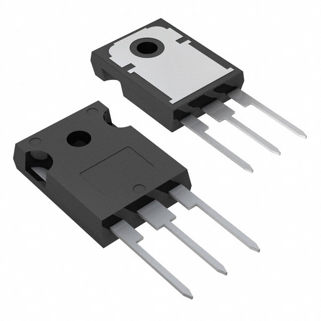
The STW80NF55-08 is an N-Channel MOSFET manufactured by STMicroelectronics, rated for 55V drain-to-source voltage and 80A continuous drain current in a TO-247-3 through-hole package. This device is part of the STripFET™ series and is classified as obsolete. Due to its obsolete status, equivalent and substitute parts from active manufacturers are necessary for new designs and ongoing production requirements. Substitute parts must maintain electrical compatibility across critical parameters including voltage rating, current capacity, on-resistance characteristics, and thermal performance while accommodating package and series variations.
Substiute Parts
Key Parameters
| Parameter | Value | Unit |
|---|---|---|
| Drain-to-Source Voltage (Vdss) | 55 | V |
| Continuous Drain Current (Id) @ 25°C | 80 | A |
| On-Resistance (Rds On Max) @ Id, Vgs | 8 mOhm @ 40A, 10V | mOhm |
| Gate Threshold Voltage (Vgs(th) Max) @ Id | 4 | V @ 250µA |
| Gate Charge (Qg Max) @ Vgs | 150 | nC @ 10V |
| Maximum Gate Voltage (Vgs Max) | ±20 | V |
| Input Capacitance (Ciss Max) @ Vds | 3850 | pF @ 25V |
| Power Dissipation (Max) | 300 | W |
| Operating Temperature Range | -55 to 175 | °C |
| Package Type | TO-247-3 | Through Hole |
| RoHS Status | ROHS3 Compliant | — |
Substitute Part Grouping Explanation
Substitution of the STW80NF55-08 is determined by strict adherence to the following electrical and mechanical parameters:
Primary Compatibility Criteria:
- Drain-to-Source Voltage (Vdss): Must equal 55V
- Package Type: Must be TO-247-3 or compatible through-hole variant
- FET Type: Must be N-Channel MOSFET
- Gate Threshold Voltage (Vgs(th)): Must equal 4V @ 250µA
- Maximum Gate Voltage (Vgs Max): Must equal ±20V
- Operating Temperature Range: Must span -55°C to 175°C
Secondary Compatibility Parameters:
- Continuous Drain Current (Id): Substitute must meet or exceed 80A
- On-Resistance (Rds On): Substitute must not exceed 8 mOhm at rated conditions
- Power Dissipation: Substitute must support thermal requirements of application
- Gate Charge (Qg): Lower values reduce switching losses; higher values acceptable if circuit design accommodates
- Input Capacitance (Ciss): Variations acceptable within circuit design tolerances
All substitute parts listed maintain the 55V voltage rating and TO-247-3 package compatibility. Variations in current rating, on-resistance, and power dissipation reflect different device generations and manufacturing series (UltraFET™, HEXFET®) while preserving functional equivalence for the primary electrical specifications.
Parameter Comparison
| Parameter | STW80NF55-08 | HUF75344G3 | HUF75345G3 | IRFP054NPBF | IRFP064NPBF | IRFP1405PBF |
|---|---|---|---|---|---|---|
| Manufacturer | STMicroelectronics | onsemi | onsemi | Infineon Technologies | Infineon Technologies | Infineon Technologies |
| Product Status | Obsolete | Active | Active | Not For New Designs | Active | Active |
| Vdss (V) | 55 | 55 | 55 | 55 | 55 | 55 |
| Id @ 25°C (A) | 80 | 75 | 75 | 81 | 110 | 95 |
| Rds On Max @ Id, Vgs (mOhm) | 8 @ 40A, 10V | 8 @ 75A, 10V | 7 @ 75A, 10V | 12 @ 43A, 10V | 8 @ 59A, 10V | 5.3 @ 95A, 10V |
| Vgs(th) Max @ Id (V) | 4 @ 250µA | 4 @ 250µA | 4 @ 250µA | 4 @ 250µA | 4 @ 250µA | 4 @ 250µA |
| Vgs Max (V) | ±20 | ±20 | ±20 | ±20 | ±20 | ±20 |
| Qg Max @ Vgs (nC) | 150 @ 10V | 210 @ 20V | 275 @ 20V | 130 @ 10V | 170 @ 10V | 180 @ 10V |
| Ciss Max @ Vds (pF) | 3850 @ 25V | 3200 @ 25V | 4000 @ 25V | 2900 @ 25V | 4000 @ 25V | 5600 @ 25V |
| Power Dissipation Max (W) | 300 | 285 | 325 | 170 | 200 | 310 |
| Operating Temperature (°C) | -55 to 175 | -55 to 175 | -55 to 175 | -55 to 175 | -55 to 175 | -55 to 175 |
| Package | TO-247-3 | TO-247-3 | TO-247-3 | TO-247AC | TO-247AC | TO-247AC |
| RoHS Status | ROHS3 Compliant | ROHS3 Compliant | ROHS3 Compliant | ROHS3 Compliant | ROHS3 Compliant | ROHS3 Compliant |
Engineering Selection Recommendations
Primary Substitutes (Active Product Status):
The HUF75345G3 and IRFP064NPBF are recommended as primary substitutes due to active product status and full compliance with RoHS3 and REACH requirements. Both devices maintain the 55V voltage rating and TO-247-3 package compatibility. The HUF75345G3 (onsemi UltraFET™ series) provides superior on-resistance performance (7 mOhm) and higher power dissipation capability (325W), making it suitable for applications requiring enhanced thermal performance. The IRFP064NPBF (Infineon HEXFET® series) offers higher current capacity (110A) and improved on-resistance characteristics (8 mOhm @ 59A), providing design margin for current-limited applications.
Secondary Substitutes (Active Product Status):
The IRFP1405PBF serves applications requiring maximum current capacity (95A) and lowest on-resistance (5.3 mOhm @ 95A) with the highest power dissipation rating (310W). This device is suitable for high-efficiency switching applications where thermal management is optimized.
Alternative Substitute (Not For New Designs):
The IRFP054NPBF is classified as "Not For New Designs" and should be used only for legacy system maintenance or replacement applications where design continuity is required. This device exhibits higher on-resistance (12 mOhm @ 43A) and lower power dissipation (170W) compared to the main part.
Marginal Substitute (Lower Current Rating):
The HUF75344G3 provides equivalent on-resistance (8 mOhm) but with reduced continuous drain current (75A) and lower power dissipation (285W). This device is suitable only for applications where the 80A current requirement can be reduced or where thermal constraints limit power dissipation.
All recommended substitutes maintain compliance with RoHS3 and REACH regulations, ensuring regulatory compatibility for production and distribution.
Frequently Asked Questions (FAQ)
Q: Can the HUF75344G3 be used as a direct replacement for the STW80NF55-08?
A: The HUF75344G3 is electrically compatible with respect to voltage rating (55V), gate threshold voltage (4V), and maximum gate voltage (±20V). However, it has a reduced continuous drain current rating (75A versus 80A) and lower power dissipation capability (285W versus 300W). It is suitable only for applications where the current requirement does not exceed 75A and thermal dissipation does not exceed 285W.
Q: What is the difference between TO-247-3 and TO-247AC packages?
A: Both TO-247-3 and TO-247AC are through-hole packages with identical pin configurations and mechanical compatibility. The designations reflect different manufacturer naming conventions. Devices in either package type are mechanically interchangeable on standard PCB layouts designed for TO-247 packages.
Q: Why does the IRFP054NPBF have higher on-resistance than the STW80NF55-08?
A: The IRFP054NPBF is an older generation HEXFET® device with on-resistance of 12 mOhm measured at 43A, compared to 8 mOhm for the STW80NF55-08 measured at 40A. This reflects advances in MOSFET manufacturing technology over successive generations. The higher on-resistance results in increased power dissipation and heat generation in switching applications.
Q: Is the IRFP1405PBF suitable for all applications requiring the STW80NF55-08?
A: The IRFP1405PBF is electrically compatible and provides superior performance characteristics including lower on-resistance (5.3 mOhm) and higher power dissipation capability (310W). It is suitable for all applications requiring the STW80NF55-08 and offers design margin for current and thermal performance. No circuit modifications are required for substitution.
Q: What is the significance of gate charge (Qg) differences between substitute parts?
A: Gate charge determines the energy required to switch the MOSFET on and off. The STW80NF55-08 has a gate charge of 150 nC @ 10V. Substitute parts with higher gate charge values (such as HUF75345G3 at 275 nC @ 20V) require more energy for switching but do not affect DC operating characteristics. Gate driver circuits must be verified to supply adequate charge current for reliable switching operation.
Q: Are all substitute parts RoHS3 compliant?
A: All substitute parts listed in this reference are RoHS3 compliant and REACH unaffected, ensuring regulatory compatibility for production and distribution in regulated markets.
Q: Can the STW80NF55-08 be replaced with a lower voltage rated device?
A: No. The 55V voltage rating is a critical parameter that must not be reduced. Using a device with lower voltage rating (such as 40V or 30V) creates risk of device failure and circuit damage when exposed to the specified 55V operating voltage.
Q: What is the impact of input capacitance (Ciss) variations on circuit performance?
A: Input capacitance affects gate drive circuit design and switching speed. The STW80NF55-08 has Ciss of 3850 pF @ 25V. Substitute parts range from 2900 pF to 5600 pF. Higher capacitance values require greater gate charge current and may slow switching transitions. Circuit design must accommodate the Ciss value of the selected substitute part to ensure stable gate drive operation.
Alternative Parts

SJ6012L2TP
Littelfuse Inc.
6 Alternative Parts

JMK107BBJ476MA-RE
Taiyo Yuden
10 Alternative Parts

GMK107BBJ475MA-T
Taiyo Yuden
5 Alternative Parts
SJ6020N2ARP
Littelfuse Inc.
3 Alternative Parts
SJ6025R2ATP
Littelfuse Inc.
4 Alternative Parts

2474-05L
API Delevan Inc.
1 Alternative Parts

4590R-684K
API Delevan Inc.
1 Alternative Parts

CM6560R-334
API Delevan Inc.
1 Alternative Parts

CM6460-104
API Delevan Inc.
1 Alternative Parts

5526-12
API Delevan Inc.
1 Alternative Parts