


Request Quote
(Ships tomorrow)
STW14NM50FD Equivalent & Substitute Parts
Part Overview
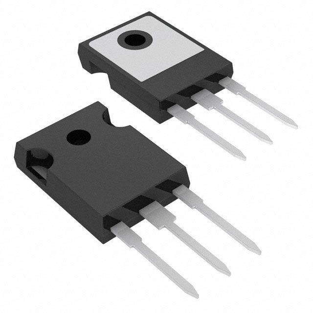
The STW14NM50FD is an N-Channel MOSFET manufactured by STMicroelectronics, rated for 500V drain-to-source voltage with 14A continuous drain current at 25°C. This device is packaged in a TO-247-3 through-hole configuration and is part of the FDmesh™ series. The part is currently classified as obsolete, making equivalent and substitute parts necessary for ongoing design support and procurement.
Substiute Parts
Key Parameters
| Parameter | Value | Unit |
|---|---|---|
| Drain to Source Voltage (Vdss) | 500 | V |
| Continuous Drain Current (Id) @ 25°C | 14 | A |
| On-State Resistance (Rds On) @ 6A, 10V | 400 | mOhm |
| Gate Threshold Voltage (Vgs(th)) @ 250µA | 5 | V |
| Gate Charge (Qg) @ 10V | 12 | nC |
| Power Dissipation (Max) | 160 | W |
| Operating Temperature Range | -65 to 150 | °C |
| Package Type | TO-247-3 | — |
| Mounting Type | Through Hole | — |
Substitute Part Grouping Explanation
Substitution of the STW14NM50FD is determined by the following critical electrical and mechanical parameters:
Primary Substitution Criteria:
- Drain-to-Source Voltage (Vdss): Must equal or exceed 500V
- Continuous Drain Current (Id): Must equal or exceed 14A at 25°C
- On-State Resistance (Rds On): Must not exceed 400mOhm at rated conditions
- Package Type: Must be TO-247-3 or compatible TO-247 variant
- Mounting Type: Must be through-hole configuration
- FET Type: Must be N-Channel MOSFET
Secondary Compatibility Parameters:
- Gate Threshold Voltage (Vgs(th)): Operating range compatibility
- Gate Charge (Qg): Affects switching speed and driver requirements
- Power Dissipation: Thermal management capability
- Operating Temperature Range: Must support application requirements
The substitute parts listed below meet or exceed the primary criteria while maintaining electrical and mechanical compatibility with the STW14NM50FD.
Parameter Comparison
| Parameter | STW14NM50FD | IRFP450LCPBF | IRFP450APBF | IRFP450PBF | IRFP448PBF | IXFH16N50P |
|---|---|---|---|---|---|---|
| Manufacturer | STMicroelectronics | Vishay Siliconix | Vishay Siliconix | Infineon Technologies | Vishay Siliconix | IXYS |
| Vdss (V) | 500 | 500 | 500 | 500 | 500 | 500 |
| Id @ 25°C (A) | 14 | 14 | 14 | 14 | 11 | 16 |
| Rds On @ 10V (mOhm) | 400 @ 6A | 400 @ 8.4A | 400 @ 8.4A | 400 @ 8.4A | 600 @ 6.6A | 400 @ 8A |
| Vgs(th) @ 250µA (V) | 5 | 4 | 4 | 4 | 4 | 5.5 |
| Qg @ 10V (nC) | 12 | 74 | 64 | 150 | 84 | 43 |
| Power Dissipation (W) | 160 | 190 | 190 | 190 | 180 | 300 |
| Operating Temperature (°C) | -65 to 150 | -55 to 150 | -55 to 150 | -55 to 150 | -55 to 150 | -55 to 150 |
| Package | TO-247-3 | TO-247AC | TO-247AC | TO-247AC | TO-247AC | TO-247AD |
| Product Status | Obsolete | Active | Active | Obsolete | Active | Active |
| RoHS3 Compliant | Yes | Yes | Yes | Yes | Yes | Yes |
Engineering Selection Recommendations
Preferred Substitutes (Active Product Status):
The IRFP450LCPBF and IRFP450APBF from Vishay Siliconix are the primary recommended substitutes. Both devices are currently in active production status, ensuring long-term availability and supply chain stability. These parts match the STW14NM50FD in critical electrical parameters: 500V Vdss, 14A continuous drain current, and 400mOhm Rds On. Both are RoHS3 compliant and REACH unaffected, meeting regulatory requirements equivalent to the original part.
The IXFH16N50P from IXYS provides superior electrical performance with 16A continuous drain current and 300W power dissipation, offering design margin for applications requiring higher current capacity or thermal headroom. This part is also in active production status.
Secondary Substitutes (Reduced Current Rating):
The IRFP448PBF is suitable for applications where the 11A continuous drain current rating is acceptable. This part carries a higher on-state resistance (600mOhm) and should be evaluated for thermal performance in the target application.
Obsolete Alternatives (Not Recommended for New Designs):
The IRFP450PBF from Infineon Technologies is classified as obsolete and should not be selected for new designs despite meeting electrical specifications. This part exhibits significantly higher gate charge (150nC) compared to the STW14NM50FD (12nC), which impacts switching speed and driver circuit design.
Compliance and Certification:
All recommended substitute parts maintain RoHS3 compliance and REACH unaffected status, ensuring regulatory alignment with the original STW14NM50FD.
Frequently Asked Questions (FAQ)
Q: Can the IRFP450LCPBF directly replace the STW14NM50FD without circuit modifications?
A: The IRFP450LCPBF is electrically compatible with the STW14NM50FD for the primary electrical specifications (Vdss, Id, Rds On). However, the gate charge differs (74nC versus 12nC), which may require driver circuit evaluation. The TO-247AC package is mechanically compatible with TO-247-3 footprints in through-hole applications.
Q: Why does the IXFH16N50P have higher gate charge (43nC) than the STW14NM50FD (12nC)?
A: Gate charge is determined by the device's internal capacitance and switching characteristics. The IXFH16N50P's higher gate charge reflects its higher current rating (16A) and power dissipation capability (300W). This parameter affects gate driver requirements but does not prevent substitution if the driver circuit can supply the required charge.
Q: Is the IRFP448PBF suitable for applications requiring 14A continuous current?
A: The IRFP448PBF is rated for 11A continuous drain current, which is below the STW14NM50FD specification of 14A. This part should only be selected if the actual application current requirement is 11A or lower, or if thermal analysis confirms adequate margin at higher currents.
Q: What is the difference between TO-247-3, TO-247AC, and TO-247AD packages?
A: All three are through-hole TO-247 variants with compatible pin configurations and footprints. The suffix designations (3, AC, AD) indicate minor variations in lead geometry and thermal characteristics. These packages are mechanically interchangeable in standard through-hole PCB designs.
Q: Why is the STW14NM50FD classified as obsolete?
A: Product obsolescence is determined by the manufacturer and typically reflects end-of-life decisions based on market demand and technology evolution. Active substitute parts from other manufacturers provide equivalent or superior performance and ensure continued design support.
Q: Should I select an active product status substitute over an obsolete one?
A: Yes. Active product status ensures long-term availability, consistent manufacturing processes, and ongoing technical support. Obsolete parts carry supply chain risk and may experience quality variations as remaining inventory is depleted.
Q: How does the operating temperature range affect substitution?
A: The STW14NM50FD operates from -65°C to 150°C, while most substitutes operate from -55°C to 150°C. If the application requires operation below -55°C, the STW14NM50FD's extended lower temperature range is necessary. For standard industrial applications (-40°C to 85°C), all substitutes are suitable.
Q: Can I use the IRFP450PBF despite its obsolete status?
A: The IRFP450PBF meets electrical specifications but is obsolete. Its significantly higher gate charge (150nC) requires careful driver circuit evaluation. For new designs, active alternatives such as IRFP450LCPBF or IXFH16N50P are preferred.
Alternative Parts

SJ6012L2TP
Littelfuse Inc.
6 Alternative Parts

JMK107BBJ476MA-RE
Taiyo Yuden
10 Alternative Parts

GMK107BBJ475MA-T
Taiyo Yuden
5 Alternative Parts
SJ6020N2ARP
Littelfuse Inc.
3 Alternative Parts
SJ6025R2ATP
Littelfuse Inc.
4 Alternative Parts

2474-05L
API Delevan Inc.
1 Alternative Parts

4590R-684K
API Delevan Inc.
1 Alternative Parts

CM6560R-334
API Delevan Inc.
1 Alternative Parts

CM6460-104
API Delevan Inc.
1 Alternative Parts

5526-12
API Delevan Inc.
1 Alternative Parts