


Request Quote
(Ships tomorrow)
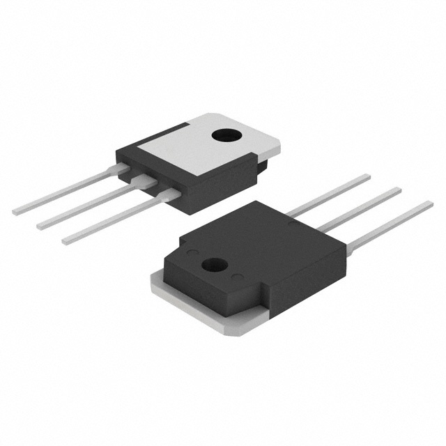
STW120NF10 N-Channel MOSFET 100V 110A TO-247-3 Equivalent & Substitute Parts
Part Overview
The STW120NF10 is an N-Channel MOSFET manufactured by STMicroelectronics in the STripFET™ II series. This device is rated for 100V drain-to-source voltage with 110A continuous drain current at 25°C and 312W maximum power dissipation. The part features a through-hole TO-247-3 package configuration.
The STW120NF10 is classified as obsolete. Equivalent and substitute parts are necessary to maintain design continuity and ensure component availability for new production builds, repairs, and system upgrades. Substitute devices must maintain electrical compatibility across critical parameters including voltage rating, current capacity, on-resistance characteristics, and thermal performance while accommodating package variations where applicable.
Substiute Parts
Key Parameters
| Parameter | Value | Unit |
|---|---|---|
| Drain-to-Source Voltage (Vdss) | 100 | V |
| Continuous Drain Current (Id) @ 25°C | 110 | A (Tc) |
| On-Resistance (Rds On) @ 60A, 10V | 10.5 | mOhm |
| Gate Threshold Voltage (Vgs(th)) @ 250µA | 4 | V |
| Gate Charge (Qg) @ 10V | 233 | nC |
| Maximum Gate Voltage (Vgs) | ±20 | V |
| Input Capacitance (Ciss) @ 25V | 5200 | pF |
| Power Dissipation (Max) | 312 | W (Tc) |
| Operating Temperature Range | -55 to 175 | °C (TJ) |
| Package Type | TO-247-3 | Through Hole |
| Technology | MOSFET (Metal Oxide) | N-Channel |
Substitute Part Grouping Explanation
Substitution of the STW120NF10 is determined by strict adherence to the following electrical and mechanical parameters:
Primary Substitution Criteria:
- Drain-to-Source Voltage (Vdss): Must equal or exceed 100V
- Continuous Drain Current (Id): Must equal or exceed 110A at 25°C
- On-Resistance (Rds On): Must not exceed 10.5mOhm at rated conditions
- Gate Threshold Voltage (Vgs(th)): Must be compatible at 4V nominal
- Maximum Gate Voltage (Vgs): Must support ±20V operation
- Operating Temperature Range: Must span -55°C to 175°C
- Technology: N-Channel MOSFET (Metal Oxide)
- Mounting Type: Through Hole configuration
Package Considerations: Substitutes are grouped into two categories based on package type:
- Direct Package Match (TO-247-3): Parts maintaining identical TO-247-3 footprint
- Alternative Through-Hole Packages: Parts with different through-hole packages (TO-220, TO-247AC, TO-247AD, TO-264AA, ISOPLUS247™) that may require PCB layout modification
Manufacturer Recommended Substitute: The STP120NF10 from STMicroelectronics provides identical electrical specifications with the same STripFET™ II series technology but in a TO-220 package. This part is active and maintains full compatibility with the electrical requirements of the STW120NF10.
Similar Substitutes: Additional substitutes from IXYS and Infineon Technologies meet or exceed the electrical specifications. These parts are grouped by their ability to satisfy the core parameters while offering variations in gate charge, input capacitance, and power dissipation characteristics.
Parameter Comparison
| Part Number | Manufacturer | Vdss (V) | Id @ 25°C (A) | Rds On (mOhm) | Vgs(th) (V) | Qg (nC) | Ciss (pF) | Pd Max (W) | Package | Status |
|---|---|---|---|---|---|---|---|---|---|---|
| STW120NF10 | STMicroelectronics | 100 | 110 | 10.5 @ 60A | 4 @ 250µA | 233 @ 10V | 5200 @ 25V | 312 | TO-247-3 | Obsolete |
| STP120NF10 | STMicroelectronics | 100 | 110 | 10.5 @ 60A | 4 @ 250µA | 233 @ 10V | 5200 @ 25V | 312 | TO-220 | Active |
| FDH3632 | onsemi | 100 | 80 | 9 @ 80A | 4 @ 250µA | 110 @ 10V | 6000 @ 25V | 310 | TO-247-3 | Active |
| HUF75652G3 | onsemi | 100 | 75 | 8 @ 75A | 4 @ 250µA | 475 @ 20V | 7585 @ 25V | 515 | TO-247-3 | Active |
| IRFP4110PBF | Infineon Technologies | 100 | 120 | 4.5 @ 75A | 4 @ 250µA | 210 @ 10V | 9620 @ 50V | 370 | TO-247AC | Active |
| IXFH110N10P | IXYS | 100 | 110 | 15 @ 500mA | 5 @ 4mA | 110 @ 10V | 3550 @ 25V | 480 | TO-247AD | Active |
| IXFH140N10P | IXYS | 100 | 140 | 11 @ 70A | 5 @ 4mA | 155 @ 10V | 4700 @ 25V | 600 | TO-247AD | Active |
| IXFH170N10P | IXYS | 100 | 170 | 9 @ 500mA | 5 @ 4mA | 198 @ 10V | 6000 @ 25V | 715 | TO-247AD | Active |
| IXFK170N10P | IXYS | 100 | 170 | 9 @ 500mA | 5 @ 4mA | 198 @ 10V | 6000 @ 25V | 715 | TO-264AA | Active |
| IXFR200N10P | IXYS | 100 | 133 | 9 @ 100A | 5 @ 8mA | 235 @ 10V | 7600 @ 25V | 300 | ISOPLUS247™ | Active |
| IXTK170N10P | IXYS | 100 | 170 | 9 @ 500mA | 5 @ 250µA | 198 @ 10V | 6000 @ 25V | 715 | TO-264 | Active |
Engineering Selection Recommendations
Manufacturer Recommended Substitute:
The STP120NF10 from STMicroelectronics is the primary recommended substitute. This part maintains identical electrical specifications to the STW120NF10 across all critical parameters including voltage rating, current capacity, on-resistance, and thermal performance. Both devices are manufactured by the same company using the same STripFET™ II technology platform. The STP120NF10 is currently in active production status, ensuring long-term availability and supply chain stability. The primary difference is the package configuration: STP120NF10 uses TO-220 instead of TO-247-3. This substitution requires PCB layout modification to accommodate the different pin footprint and thermal characteristics of the TO-220 package.
Active Substitute Options:
For applications requiring TO-247-3 package retention, the following active substitutes are available:
-
IRFP4110PBF (Infineon Technologies, HEXFET® series): Exceeds the STW120NF10 specifications with 120A continuous current and superior on-resistance of 4.5mOhm at 75A. This part offers enhanced thermal performance with 370W power dissipation. The TO-247AC package is mechanically compatible with TO-247-3 footprints. RoHS3 compliant and MSL Level 1.
-
IXFH110N10P (IXYS, HiPerFET™ series): Matches the 110A current rating in TO-247AD package. This part maintains the same voltage and current specifications as the original device. RoHS3 compliant and MSL Level 1.
-
IXFH140N10P (IXYS, HiPerFET™ series): Provides 140A continuous current capability with 11mOhm on-resistance, exceeding the STW120NF10 performance envelope. TO-247AD package. RoHS3 compliant and MSL Level 1.
-
IXFH170N10P (IXYS, HiPerFET™ series): Delivers 170A continuous current with 9mOhm on-resistance and 715W power dissipation. TO-247AD package. RoHS3 compliant and MSL Level 1. Highest inventory availability (688,100 units).
Alternative Package Substitutes:
For applications where package flexibility exists:
- IXFK170N10P (IXYS, TO-264AA): Identical electrical specifications to IXFH170N10P with alternative through-hole package.
- IXTK170N10P (IXYS, TO-264): Identical electrical specifications with TO-264 package option.
- IXFR200N10P (IXYS, ISOPLUS247™): 133A continuous current with 9mOhm on-resistance in specialized isolated package.
Compliance Status:
All recommended substitutes maintain RoHS3 compliance and REACH unaffected status, matching the regulatory requirements of the original STW120NF10. All parts are classified under ECCN EAR99 and HTSUS 8541.29.0095.
Frequently Asked Questions (FAQ)
Q: Can the STP120NF10 be used as a direct replacement for the STW120NF10?
A: The STP120NF10 provides identical electrical specifications and is manufactured by the same company using the same technology. However, the package differs: STP120NF10 uses TO-220 while STW120NF10 uses TO-247-3. Direct PCB substitution is not possible without layout modification. The TO-220 package has a different pin footprint and thermal interface characteristics. Thermal management design must be re-evaluated for the TO-220 configuration.
Q: What is the primary difference between TO-247-3 and TO-247AC packages?
A: Both TO-247-3 and TO-247AC are mechanically and electrically compatible through-hole packages with identical pin configurations and footprints. The designations reflect minor manufacturing or supplier variations. Parts specified as TO-247AC (such as IRFP4110PBF) can be used in applications designed for TO-247-3 without PCB modification.
Q: Why do some substitute parts have higher gate charge (Qg) values?
A: Gate charge represents the total charge required to switch the transistor from off to on state. Higher gate charge values (such as 475nC in HUF75652G3 versus 233nC in STW120NF10) indicate different internal gate structure designs. This affects switching speed and driver circuit requirements. Parts with higher gate charge may require higher gate drive current or longer switching times. Verify gate driver compatibility before substitution.
Q: Is the IXFH170N10P suitable for applications requiring exactly 110A continuous current?
A: The IXFH170N10P is rated for 170A continuous current, which exceeds the 110A requirement of the STW120NF10. This part is suitable for applications requiring 110A operation. The higher current rating provides design margin and does not create incompatibility. However, the on-resistance specification (9mOhm at 500mA) differs from the STW120NF10 specification (10.5mOhm at 60A), reflecting different measurement conditions. Verify thermal performance in your specific application.
Q: Can I use a substitute part with lower on-resistance than the STW120NF10?
A: Yes. Lower on-resistance (Rds On) is beneficial as it reduces power dissipation and heat generation. Parts such as IRFP4110PBF (4.5mOhm) and IXFH170N10P (9mOhm) offer improved performance compared to the STW120NF10 (10.5mOhm). Lower on-resistance reduces conduction losses and improves overall circuit efficiency. No design modifications are required to accommodate lower on-resistance.
Q: What is the significance of the ±20V maximum gate voltage specification?
A: The ±20V Vgs(max) specification indicates the maximum voltage that can be safely applied to the gate terminal relative to the source. All recommended substitutes maintain this ±20V rating, ensuring compatibility with existing gate drive circuits. Exceeding this voltage can cause permanent gate oxide damage. Verify that your gate driver circuit does not exceed ±20V under any operating condition.
Q: Are all substitute parts RoHS3 compliant?
A: Yes. All recommended substitute parts listed in this document are RoHS3 compliant and REACH unaffected, matching the regulatory status of the original STW120NF10. This ensures compatibility with environmental and regulatory requirements for new production builds.
Q: What is the difference between TO-247AD and TO-247-3 packages?
A: TO-247AD is a variant of the TO-247 package family with identical electrical and mechanical pin configurations. The "AD" designation indicates a specific supplier or manufacturing variant. Parts specified as TO-247AD (such as IXYS HiPerFET™ devices) are mechanically compatible with TO-247-3 footprints and can be used as direct package substitutes without PCB modification.
Q: Why is the IXFH170N10P available in such high inventory (688,100 units)?
A: High inventory levels indicate strong market demand and active production status. The IXFH170N10P is a popular industrial-grade MOSFET used across multiple applications. High availability reduces lead times and supply chain risk, making it a reliable choice for new designs and production builds.
Q: Can I substitute a part with higher power dissipation rating?
A: Yes. Higher power dissipation ratings (such as 715W in IXFH170N10P versus 312W in STW120NF10) indicate improved thermal performance and design margin. This does not create incompatibility. However, verify that your PCB thermal design and heat sink are adequate for the actual power dissipation in your application. Higher power rating does not automatically mean higher actual power dissipation in your circuit.
Q: What should I verify before implementing a substitute part?
A: Before substitution, verify: (1) Gate drive voltage compatibility with ±20V maximum specification, (2) PCB footprint compatibility with the selected package type, (3) Thermal management adequacy for the substitute part's power dissipation characteristics, (4) On-resistance and switching speed compatibility with your circuit timing requirements, (5) Input capacitance compatibility with your gate driver circuit current capability, and (6) Operating temperature range suitability for your application environment.
Alternative Parts

SJ6012L2TP
Littelfuse Inc.
6 Alternative Parts

JMK107BBJ476MA-RE
Taiyo Yuden
10 Alternative Parts

GMK107BBJ475MA-T
Taiyo Yuden
5 Alternative Parts
SJ6020N2ARP
Littelfuse Inc.
3 Alternative Parts
SJ6025R2ATP
Littelfuse Inc.
4 Alternative Parts

2474-05L
API Delevan Inc.
1 Alternative Parts

4590R-684K
API Delevan Inc.
1 Alternative Parts

CM6560R-334
API Delevan Inc.
1 Alternative Parts

CM6460-104
API Delevan Inc.
1 Alternative Parts

5526-12
API Delevan Inc.
1 Alternative Parts