


Request Quote
(Ships tomorrow)
STW11NB80 Equivalent & Substitute Parts
Part Overview
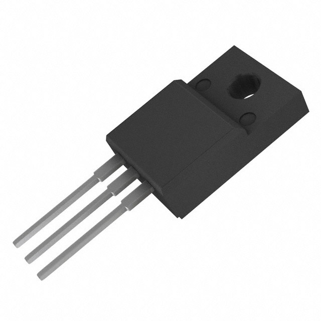
The STW11NB80 is an N-Channel MOSFET manufactured by STMicroelectronics, rated for 800V drain-to-source voltage with 11A continuous drain current at 25°C. This device is packaged in TO-247-3 and belongs to the PowerMESH™ series. The part is classified as obsolete, making equivalent and substitute parts necessary for ongoing system support and new procurement activities. Identifying compatible alternatives ensures design continuity and supply chain flexibility for applications requiring high-voltage switching functionality.
Substiute Parts
Key Parameters
| Parameter | Value | Unit |
|---|---|---|
| Drain to Source Voltage (Vdss) | 800 | V |
| Continuous Drain Current (Id) @ 25°C | 11 | A |
| On-State Resistance (Rds On Max) @ 10V | 800 | mOhm |
| Gate Threshold Voltage (Vgs th) @ 250µA | 5 | V |
| Gate Charge (Qg) @ 10V | 70 | nC |
| Power Dissipation (Max) | 190 | W |
| Operating Temperature (TJ) | 150 | °C |
| Package Type | TO-247-3 | — |
| Mounting Type | Through Hole | — |
| Product Status | Obsolete | — |
Substitute Part Grouping Explanation
Substitution of the STW11NB80 is determined by the following critical electrical and mechanical parameters:
Primary Matching Criteria:
- Drain-to-Source Voltage (Vdss): 800V minimum
- Continuous Drain Current (Id): 11A or greater at 25°C
- Gate Drive Voltage: 10V
- Package/Mounting: Through-hole configuration compatible with TO-247-3 footprint
- Gate Threshold Voltage (Vgs th): 5V nominal at specified test current
Secondary Compatibility Factors:
- On-State Resistance (Rds On): Lower values indicate improved performance; values up to 800mOhm are acceptable
- Gate Charge (Qg): Values within ±30% of 70nC maintain switching characteristics
- Power Dissipation: Minimum 156W to support thermal requirements
- Operating Temperature Range: Minimum 150°C junction temperature
The three substitute parts listed below meet these criteria with varying degrees of parameter alignment and product status compliance.
Parameter Comparison
| Parameter | STW11NB80 | FQAF13N80 | IXFR20N80P | SPW11N80C3FKSA1 |
|---|---|---|---|---|
| Manufacturer | STMicroelectronics | onsemi | IXYS | Infineon Technologies |
| Vdss (V) | 800 | 800 | 800 | 800 |
| Id @ 25°C (A) | 11 | 8 | 11 | 11 |
| Rds On Max @ 10V (mOhm) | 800 | 750 | 500 | 450 |
| Vgs(th) @ Test Current (V) | 5 @ 250µA | 5 @ 250µA | 5 @ 4mA | 3.9 @ 680µA |
| Gate Charge Qg @ 10V (nC) | 70 | 88 | 85 | 85 |
| Power Dissipation Max (W) | 190 | 120 | 166 | 156 |
| Operating Temperature TJ (°C) | 150 | -55 to 150 | -55 to 150 | -55 to 150 |
| Package | TO-247-3 | TO-3P-3 | ISOPLUS247™ | PG-TO247-3-1 |
| Product Status | Obsolete | Obsolete | Active | Not For New Designs |
| RoHS Status | Non-compliant | ROHS3 Compliant | ROHS3 Compliant | ROHS3 Compliant |
Engineering Selection Recommendations
IXFR20N80P (IXYS)
The IXFR20N80P is the primary substitute for new procurement and active system support. This part maintains identical voltage and current ratings (800V, 11A) with superior on-state resistance (500mOhm versus 800mOhm), resulting in lower power dissipation and improved thermal performance. The device is in active product status with ROHS3 compliance, ensuring long-term availability and regulatory alignment. The ISOPLUS247™ package is mechanically compatible with TO-247-3 footprints. Operating temperature range extends to -55°C, providing broader environmental coverage than the original part.
SPW11N80C3FKSA1 (Infineon Technologies)
The SPW11N80C3FKSA1 offers the lowest on-state resistance (450mOhm) among available substitutes, delivering the best thermal efficiency. This CoolMOS™ series device matches the 800V/11A ratings and maintains TO-247-3 package compatibility. ROHS3 compliance and extended operating temperature range (-55°C to 150°C) are provided. However, the product status is classified as "Not For New Designs," limiting its suitability for new development projects. This part is appropriate for legacy system maintenance and repair applications where existing inventory is available.
FQAF13N80 (onsemi)
The FQAF13N80 is not recommended as a primary substitute due to reduced continuous drain current (8A versus 11A). While the part meets the 800V voltage requirement and provides ROHS3 compliance, the lower current rating restricts its application to systems with reduced power demands. The TO-3P-3 package differs from the original TO-247-3, requiring PCB layout modifications. This part is classified as obsolete, offering no advantage over the original device for new procurement.
Frequently Asked Questions (FAQ)
Q: Can the FQAF13N80 be used as a direct replacement for the STW11NB80?
A: The FQAF13N80 is not a direct replacement. While both devices operate at 800V, the FQAF13N80 is rated for only 8A continuous drain current compared to the STW11NB80's 11A rating. Applications requiring the full 11A current capacity will experience reduced performance or potential device failure. Additionally, the TO-3P-3 package differs from the TO-247-3, requiring PCB modifications.
Q: What is the primary advantage of the IXFR20N80P over the original STW11NB80?
A: The IXFR20N80P provides superior on-state resistance (500mOhm versus 800mOhm), resulting in lower power dissipation and reduced thermal stress. The device maintains identical voltage and current ratings while offering active product status, ensuring long-term availability. The ISOPLUS247™ package is mechanically compatible with TO-247-3 footprints without requiring PCB redesign.
Q: Are all substitute parts RoHS compliant?
A: The IXFR20N80P and SPW11N80C3FKSA1 are ROHS3 compliant. The FQAF13N80 is also ROHS3 compliant. The original STW11NB80 is RoHS non-compliant. For applications requiring regulatory compliance, the substitute parts provide the necessary certification.
Q: Can the SPW11N80C3FKSA1 be used in new designs?
A: The SPW11N80C3FKSA1 is classified as "Not For New Designs" by Infineon Technologies. While the device is technically functional and available in inventory, this status indicates the manufacturer does not recommend its use in new development projects. The IXFR20N80P is the preferred choice for new designs due to its active product status.
Q: What is the impact of different gate charge values on circuit performance?
A: Gate charge (Qg) affects switching speed and gate drive circuit requirements. The STW11NB80 has a gate charge of 70nC, while substitutes range from 85nC to 88nC. These differences are within acceptable engineering tolerances and do not require gate drive circuit modifications for most applications. Higher gate charge values result in slightly longer switching transitions but do not compromise functional compatibility.
Q: Are package modifications required when substituting the IXFR20N80P?
A: The IXFR20N80P uses the ISOPLUS247™ package, which maintains TO-247-3 footprint compatibility. No PCB layout modifications are required for this substitution. The mechanical pin configuration and mounting hole spacing are identical to the original TO-247-3 package.
Q: How do operating temperature ranges affect part selection?
A: The STW11NB80 specifies a maximum junction temperature of 150°C without a minimum operating temperature. The IXFR20N80P and SPW11N80C3FKSA1 both specify -55°C to 150°C operating ranges, providing broader environmental coverage. For applications operating at temperatures below 0°C, these substitutes offer superior performance characteristics.
Alternative Parts

SJ6012L2TP
Littelfuse Inc.
6 Alternative Parts

JMK107BBJ476MA-RE
Taiyo Yuden
10 Alternative Parts

GMK107BBJ475MA-T
Taiyo Yuden
5 Alternative Parts
SJ6020N2ARP
Littelfuse Inc.
3 Alternative Parts
SJ6025R2ATP
Littelfuse Inc.
4 Alternative Parts

2474-05L
API Delevan Inc.
1 Alternative Parts

4590R-684K
API Delevan Inc.
1 Alternative Parts

CM6560R-334
API Delevan Inc.
1 Alternative Parts

CM6460-104
API Delevan Inc.
1 Alternative Parts

5526-12
API Delevan Inc.
1 Alternative Parts