


Request Quote
(Ships tomorrow)
STU12N60M2 Equivalent & Substitute Parts
Part Overview
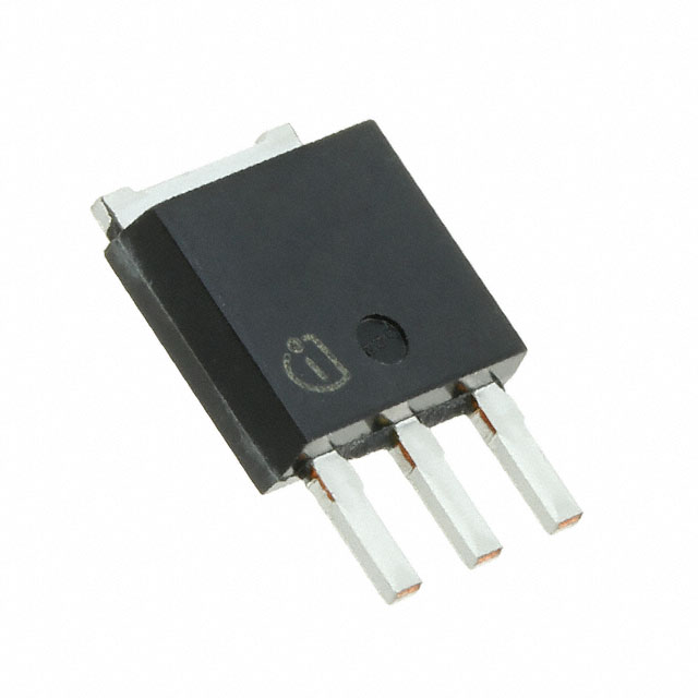
The STU12N60M2 is an N-Channel MOSFET manufactured by STMicroelectronics, rated for 600V drain-to-source voltage with 9A continuous drain current at 25°C. The device is housed in a TO-251 (IPAK) through-hole package and is designed for high-voltage switching applications. This part is currently Active in product status with 6432 units in stock.
Substitute parts are identified when equivalent electrical performance can be achieved within the specified parameter tolerances, accounting for differences in voltage rating, current capacity, and thermal characteristics. The STU12N60M2 operates across a -55°C to 150°C temperature range with a maximum power dissipation of 85W at the case temperature.
Substiute Parts
Key Parameters
| Parameter | Value | Unit |
|---|---|---|
| Drain-to-Source Voltage (Vdss) | 600 | V |
| Continuous Drain Current (Id) @ 25°C | 9 | A |
| On-State Resistance (Rds On Max) @ 4.5A, 10V | 450 | mOhm |
| Gate Threshold Voltage (Vgs(th) Max) @ 250µA | 4 | V |
| Gate Charge (Qg Max) @ 10V | 16 | nC |
| Power Dissipation (Max) | 85 | W |
| Operating Temperature Range | -55 to 150 | °C |
| Package Type | TO-251-3 (IPAK) | Through Hole |
| Series | MDmesh™ M2 |
Substitute Part Grouping Explanation
Substitution eligibility for the STU12N60M2 is determined by the following critical parameters:
Voltage Rating Compatibility: The substitute part must support the application's maximum voltage requirement. The STU12N60M2 is rated at 600V Vdss. A substitute with a higher voltage rating (such as 800V) is acceptable for 600V applications, as it provides additional voltage margin. A lower voltage rating is not acceptable.
Current Capacity: The substitute must deliver continuous drain current sufficient for the application. The STU12N60M2 provides 9A at 25°C. Substitutes with equal or greater current capacity are acceptable.
On-State Resistance (Rds On): This parameter directly affects power dissipation and switching losses. The STU12N60M2 specifies 450mOhm maximum at 4.5A and 10V gate drive. Substitutes with comparable or lower Rds On values maintain thermal performance.
Package and Mounting: The STU12N60M2 uses TO-251-3 (IPAK) through-hole packaging. Substitutes must use identical or mechanically compatible package types to ensure PCB layout compatibility.
Temperature Range: The STU12N60M2 operates from -55°C to 150°C. Substitutes must support this full range.
Compliance and Status: RoHS3 compliance and REACH unaffected status are required for regulatory alignment.
Parameter Comparison
| Parameter | STU12N60M2 (Main) | IPS80R600P7AKMA1 (Substitute) | Unit |
|---|---|---|---|
| Manufacturer | STMicroelectronics | Infineon Technologies | |
| FET Type | N-Channel | N-Channel | |
| Technology | MOSFET (Metal Oxide) | MOSFET (Metal Oxide) | |
| Drain-to-Source Voltage (Vdss) | 600 | 800 | V |
| Continuous Drain Current (Id) @ 25°C | 9 | 8 | A |
| On-State Resistance (Rds On Max) | 450 @ 4.5A, 10V | 600 @ 3.4A, 10V | mOhm |
| Gate Threshold Voltage (Vgs(th) Max) | 4 @ 250µA | 3.5 @ 170µA | V |
| Gate Charge (Qg Max) @ 10V | 16 | 20 | nC |
| Maximum Gate Voltage (Vgs Max) | ±25 | ±20 | V |
| Power Dissipation (Max) | 85 | 60 | W |
| Operating Temperature Range | -55 to 150 | -55 to 150 | °C |
| Package Type | TO-251-3 Short Leads (IPAK) | TO-251-3 Stub Leads (IPAK) | |
| RoHS Status | ROHS3 Compliant | ROHS3 Compliant | |
| REACH Status | REACH Unaffected | REACH Unaffected | |
| Product Status | Active | Discontinued at DiGi Electronics |
Engineering Selection Recommendations
Primary Selection: The STU12N60M2 remains the preferred choice for new designs. It is Active in product status with substantial inventory availability (6432 units in stock), ensuring long-term supply continuity. The part meets all RoHS3 and REACH compliance requirements.
Substitute Consideration: The IPS80R600P7AKMA1 (Infineon Technologies CoolMOS™ P7 series) is electrically compatible for applications where the STU12N60M2 is unavailable. This substitute provides the following characteristics:
The IPS80R600P7AKMA1 has a higher voltage rating (800V versus 600V), which is acceptable for 600V applications and provides additional voltage headroom. However, the continuous drain current is reduced to 8A compared to the STU12N60M2's 9A, which may limit applications requiring the full 9A capacity.
The on-state resistance of the IPS80R600P7AKMA1 is higher (600mOhm versus 450mOhm), resulting in increased power dissipation at equivalent current levels. The maximum power dissipation rating is also lower (60W versus 85W), which may constrain thermal performance in high-power applications.
Both devices share identical operating temperature ranges (-55°C to 150°C) and comply with RoHS3 and REACH requirements. Both use TO-251-3 IPAK through-hole packaging, though the IPS80R600P7AKMA1 uses stub leads while the STU12N60M2 uses short leads. This lead configuration difference requires PCB layout verification for mechanical fit.
Critical Limitation: The IPS80R600P7AKMA1 is discontinued at DiGi Electronics, limiting its availability for future procurement. This status restricts its use to applications where existing inventory is accessible or where alternative sourcing channels are established.
Frequently Asked Questions (FAQ)
Q: Can the IPS80R600P7AKMA1 directly replace the STU12N60M2 in all applications?
A: The IPS80R600P7AKMA1 is electrically compatible for voltage and temperature requirements. However, the reduced continuous drain current (8A versus 9A) and higher on-state resistance (600mOhm versus 450mOhm) may affect performance in applications operating at or near the STU12N60M2's rated current. Thermal analysis is required to confirm the lower power dissipation rating (60W versus 85W) is acceptable for the specific application.
Q: What is the difference between TO-251-3 short leads and stub leads?
A: Both variants use the TO-251-3 (IPAK) package outline. Short leads and stub leads refer to the physical length of the leads extending from the package body. This difference affects PCB hole spacing and lead insertion depth. PCB layout must be verified to ensure mechanical compatibility with the specific lead variant being used.
Q: Is the IPS80R600P7AKMA1 suitable for new product designs?
A: The IPS80R600P7AKMA1 is discontinued at DiGi Electronics, making it unsuitable for new designs requiring long-term supply assurance. The STU12N60M2 is the recommended choice for new product development due to its Active status and available inventory.
Q: What are the compliance differences between these parts?
A: Both the STU12N60M2 and IPS80R600P7AKMA1 are RoHS3 compliant and REACH unaffected. No compliance differentiation exists between these parts.
Q: How does the higher voltage rating of the IPS80R600P7AKMA1 affect circuit design?
A: The 800V rating of the IPS80R600P7AKMA1 provides additional voltage margin above the 600V application requirement. This does not negatively affect circuit operation in 600V applications. However, the higher gate charge (20nC versus 16nC) may require gate driver adjustments to maintain switching speed performance.
Q: What inventory considerations apply to these parts?
A: The STU12N60M2 has 6432 units in stock, providing immediate availability. The IPS80R600P7AKMA1 has 687 units in stock but is discontinued at DiGi Electronics, limiting future procurement options. For applications requiring long-term supply, the STU12N60M2 is the appropriate selection.
Alternative Parts

SJ6012L2TP
Littelfuse Inc.
6 Alternative Parts

JMK107BBJ476MA-RE
Taiyo Yuden
10 Alternative Parts

GMK107BBJ475MA-T
Taiyo Yuden
5 Alternative Parts
SJ6020N2ARP
Littelfuse Inc.
3 Alternative Parts
SJ6025R2ATP
Littelfuse Inc.
4 Alternative Parts

2474-05L
API Delevan Inc.
1 Alternative Parts

4590R-684K
API Delevan Inc.
1 Alternative Parts

CM6560R-334
API Delevan Inc.
1 Alternative Parts

CM6460-104
API Delevan Inc.
1 Alternative Parts

5526-12
API Delevan Inc.
1 Alternative Parts