


Request Quote
(Ships tomorrow)
STPS30SM60CT Equivalent & Substitute Parts
Part Overview
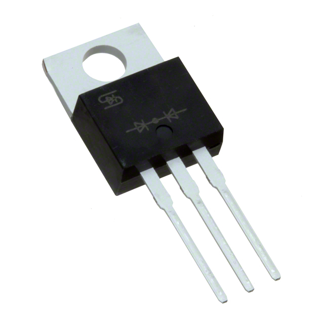
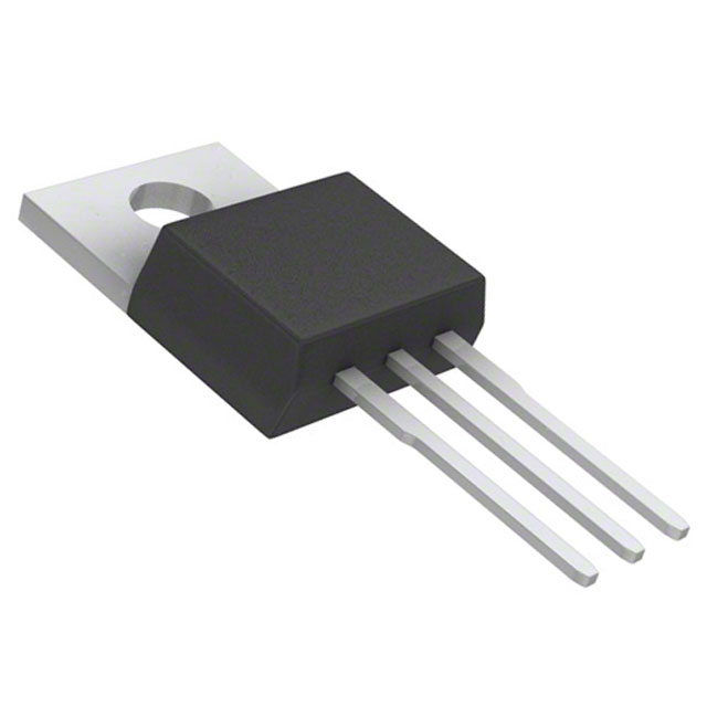
The STPS30SM60CT is a Schottky diode array manufactured by STMicroelectronics, configured as 1 pair common cathode with 60 V reverse voltage rating and 15 A average rectified current per diode. The device is packaged in TO-220-3 through-hole format and is classified as obsolete. Due to its obsolete status, equivalent and substitute parts from active manufacturers are necessary for new designs and ongoing production requirements. Substitute parts maintain the core electrical specifications while offering improved availability and extended product lifecycles.
Substiute Parts
Key Parameters
| Parameter | Value | Unit |
|---|---|---|
| Diode Configuration | 1 Pair Common Cathode | — |
| Technology | Schottky | — |
| Voltage - DC Reverse (Vr) (Max) | 60 | V |
| Current - Average Rectified (Io) (per Diode) | 15 | A |
| Voltage - Forward (Vf) (Max) @ If | 625 mV @ 15 A | — |
| Speed | Fast Recovery ≤ 500ns, > 200mA (Io) | — |
| Current - Reverse Leakage @ Vr | 65 | µA @ 60 V |
| Operating Temperature - Junction (Max) | 150 | °C |
| Mounting Type | Through Hole | — |
| Package / Case | TO-220-3 | — |
| RoHS Status | ROHS3 Compliant | — |
Substitute Part Grouping Explanation
Substitution of the STPS30SM60CT is determined by the following critical parameters:
Primary Substitution Criteria:
- Diode Configuration: 1 Pair Common Cathode (mandatory match)
- Voltage - DC Reverse (Vr) (Max): 60 V (mandatory match)
- Current - Average Rectified (Io) (per Diode): 15 A minimum (equal or greater acceptable)
- Mounting Type: Through Hole (mandatory match)
- Package / Case: TO-220-3 or compatible variant (mandatory match)
- Technology: Schottky or Super Barrier (functionally equivalent)
- Speed: Fast Recovery ≤ 500ns, > 200mA (Io) (mandatory match)
Secondary Compatibility Factors:
- Voltage - Forward (Vf) (Max) @ If: Variations within ±150 mV acceptable for most applications
- Current - Reverse Leakage @ Vr: Higher leakage acceptable in non-critical applications
- Operating Temperature - Junction: Extended range acceptable
- RoHS and REACH compliance status
Substitute parts are grouped into three categories:
Direct Equivalents (15 A @ 60 V): Parts with identical current rating and voltage specification, differing primarily in forward voltage characteristics and leakage current.
Higher Current Capacity (20 A – 30 A @ 60 V): Parts with superior current handling capability, suitable for applications requiring design margin or higher load conditions.
Lower Current Capacity (5 A – 10 A @ 60 V): Parts with reduced current rating, suitable only for applications with lower current requirements than the original specification.
Parameter Comparison
| Part Number | Manufacturer | Io (A) | Vf (Max) @ If | Vr (Max) (V) | Leakage @ 60V (µA) | Tj (Max) (°C) | Package | Status |
|---|---|---|---|---|---|---|---|---|
| STPS30SM60CT | STMicroelectronics | 15 | 625 mV @ 15 A | 60 | 65 | 150 | TO-220-3 | Obsolete |
| 30CTQ060 | SMC Diode Solutions | 15 | 620 mV @ 15 A | 60 | 1000 | 175 | TO-220-3 | Active |
| MBR3060CT | Taiwan Semiconductor Corporation | 30 | 770 mV @ 15 A | 60 | 200 | 150 | TO-220-3 | Active |
| MBR3060CTP | Diodes Incorporated | 15 | 750 mV @ 15 A | 60 | 100 | 175 | TO-220-3 Isolated Tab | Obsolete |
| SBR3060CT | Diodes Incorporated | 15 | 700 mV @ 15 A | 60 | 500 | 150 | TO-220-3 | Active |
| DST2060C | Littelfuse Inc. | 10 | 645 mV @ 10 A | 60 | 850 | 150 | TO-220-3 | Active |
| DST3060LC | Littelfuse Inc. | 15 | 550 mV @ 15 A | 60 | 300 | 125 | TO-220-3 | Active |
| MBR1060CT-G1 | Diodes Incorporated | 5 | 750 mV @ 5 A | 60 | 100 | 150 | TO-220-3 | Active |
| MBR1060CTL | SMC Diode Solutions | — | 600 mV @ 5 A | 60 | 1000 | 150 | TO-220-3 | Active |
| MBR2060CT | Taiwan Semiconductor Corporation | 20 | 950 mV @ 20 A | 60 | 100 | 150 | TO-220-3 | Active |
| MBR30L60CTG | onsemi | 15 | 620 mV @ 15 A | 60 | 350 | 150 | TO-220-3 | Obsolete |
Engineering Selection Recommendations
For Direct Replacement (Active Product Status):
The 30CTQ060 (SMC Diode Solutions) and DST3060LC (Littelfuse Inc.) are primary direct equivalents with 15 A current rating and 60 V reverse voltage. Both are active products with ROHS3 compliance. The 30CTQ060 offers extended junction temperature range (−55°C to 175°C) and lower forward voltage (620 mV @ 15 A). The DST3060LC provides the lowest forward voltage (550 mV @ 15 A) among 15 A rated options, reducing power dissipation in switching applications.
For Applications Requiring Design Margin:
The MBR3060CT (Taiwan Semiconductor Corporation) provides 30 A current capacity at 60 V, offering 2× the current handling of the original part. This device is suitable for applications where future current demand or thermal margin is required. Active product status ensures long-term availability.
For Super Barrier Technology:
The SBR3060CT (Diodes Incorporated) employs Super Barrier technology with 15 A rating and 60 V specification. Forward voltage is 700 mV @ 15 A. This device is active and ROHS3 compliant, providing an alternative technology platform while maintaining electrical compatibility.
For Isolated Tab Requirement:
The MBR3060CTP (Diodes Incorporated) features TO-220-3 Isolated Tab packaging, required in applications where the tab must be electrically isolated from the cathode. Although obsolete, this part maintains 15 A / 60 V specifications with extended temperature range (−65°C to 175°C).
For Lower Current Applications:
The MBR1060CT-G1 (Diodes Incorporated) and DST2060C (Littelfuse Inc.) are suitable only for applications with maximum current requirements of 5 A and 10 A respectively. These parts are not recommended as replacements for the 15 A rated STPS30SM60CT in full-load conditions.
Compliance Considerations:
All recommended active substitutes maintain ROHS3 compliance. The 30CTQ060 and MBR3060CTP are REACH Affected; verify REACH compliance requirements for your application. All parts are classified as EAR99 for export control purposes.
Frequently Asked Questions (FAQ)
Q: Can the 30CTQ060 directly replace the STPS30SM60CT without circuit modification?
A: Yes. The 30CTQ060 maintains identical diode configuration (1 pair common cathode), voltage rating (60 V), and current rating (15 A). Forward voltage is nearly identical (620 mV vs. 625 mV @ 15 A). The TO-220-3 package is mechanically and electrically compatible. No circuit modification is required.
Q: What is the difference between Schottky and Super Barrier technology in the SBR3060CT?
A: Both technologies are fast-recovery rectifier diodes with similar electrical characteristics. Super Barrier represents an advanced Schottky variant with optimized forward voltage and leakage characteristics. The SBR3060CT exhibits 700 mV forward voltage compared to 625 mV in the original part, representing a 75 mV increase. This difference affects power dissipation in high-frequency switching applications.
Q: Why does the MBR3060CT have higher forward voltage (770 mV) than the original part?
A: The MBR3060CT is rated for 30 A continuous current, compared to 15 A in the STPS30SM60CT. Higher current capacity typically results in increased forward voltage drop due to semiconductor junction design trade-offs. The 145 mV increase (770 mV vs. 625 mV @ 15 A) reflects this design optimization for higher current handling.
Q: Is the MBR1060CTL suitable as a replacement?
A: The MBR1060CTL is not suitable as a direct replacement. While it maintains the 60 V voltage rating and TO-220-3 package, the current rating is unspecified in available data, and forward voltage is specified only at 5 A (600 mV @ 5 A). This part is designed for lower-current applications and does not guarantee 15 A performance.
Q: What is the significance of the isolated tab in the MBR3060CTP?
A: The isolated tab (ITO-220S package) electrically separates the mounting tab from the cathode terminal. Standard TO-220-3 packages connect the tab to the cathode. Isolated tab versions are required in applications where the mounting surface must be at a different potential than the cathode, such as floating gate drive circuits or isolated power supplies.
Q: Can I use the MBR3060CT (30 A) in place of the STPS30SM60CT (15 A)?
A: Yes, the MBR3060CT is electrically compatible and provides superior current capacity. However, the higher forward voltage (770 mV vs. 625 mV @ 15 A) increases power dissipation by approximately 145 mW per diode at 15 A operation. Verify that thermal design accommodates this additional dissipation. The MBR3060CT is recommended only when design margin or future current growth justifies the increased power loss.
Q: Why is the DST3060LC preferred for low-power-loss applications?
A: The DST3060LC exhibits the lowest forward voltage (550 mV @ 15 A) among all 15 A rated substitutes, reducing power dissipation by 75 mW per diode compared to the original part. This characteristic is advantageous in high-frequency switching supplies and battery charging circuits where efficiency is critical. However, the maximum junction temperature is limited to 125°C, compared to 150°C in the original part.
Q: Are all substitute parts ROHS3 compliant?
A: Yes. All substitute parts listed are ROHS3 compliant. However, REACH compliance status varies. The 30CTQ060 and MBR3060CTP are REACH Affected; verify REACH compliance requirements for your specific application and geographic market.
Q: What is the impact of higher reverse leakage current in the 30CTQ060 (1 mA vs. 65 µA)?
A: Higher reverse leakage increases standby power consumption and heat generation when the diode is reverse-biased. In most switching applications, this effect is negligible. In precision analog circuits or battery-powered systems with extended standby periods, the higher leakage (1 mA vs. 65 µA) may require thermal or power budget reassessment.
Q: Can the DST2060C (10 A) be used in a 15 A application?
A: No. The DST2060C is rated for 10 A maximum continuous current, which is 33% below the 15 A requirement of the original part. Using this device in a 15 A application will result in excessive junction temperature, reduced device lifetime, and potential thermal runaway. The DST2060C is suitable only for applications with confirmed maximum current requirements of 10 A or less.
Alternative Parts

SJ6012L2TP
Littelfuse Inc.
6 Alternative Parts

JMK107BBJ476MA-RE
Taiyo Yuden
10 Alternative Parts

GMK107BBJ475MA-T
Taiyo Yuden
5 Alternative Parts
SJ6020N2ARP
Littelfuse Inc.
3 Alternative Parts
SJ6025R2ATP
Littelfuse Inc.
4 Alternative Parts

2474-05L
API Delevan Inc.
1 Alternative Parts

4590R-684K
API Delevan Inc.
1 Alternative Parts

CM6560R-334
API Delevan Inc.
1 Alternative Parts

CM6460-104
API Delevan Inc.
1 Alternative Parts

5526-12
API Delevan Inc.
1 Alternative Parts