


Request Quote
(Ships tomorrow)
STPS20SM60SR Equivalent & Substitute Parts
Part Overview
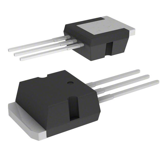
The STPS20SM60SR is a Schottky rectifier diode manufactured by STMicroelectronics, rated for 60 V DC reverse voltage and 20 A average rectified current. The device is packaged in a TO-262-3 Long Leads (I2PAK) configuration for through-hole mounting applications. This part is classified as obsolete, necessitating identification of active equivalent alternatives for continued system support and new design implementations.
Substiute Parts
Key Parameters
| Parameter | Value | Unit |
|---|---|---|
| Voltage - DC Reverse (Vr) (Max) | 60 | V |
| Current - Average Rectified (Io) | 20 | A |
| Voltage - Forward (Vf) (Max) @ If | 630 mV @ 20 A | mV |
| Speed | Fast Recovery ≤ 500ns, > 200mA (Io) | ns |
| Current - Reverse Leakage @ Vr | 85 | µA @ 60 V |
| Operating Temperature - Junction (Max) | 150 | °C |
| Package / Case | TO-262-3 Long Leads, I2PAK, TO-262AA | — |
| Mounting Type | Through Hole | — |
| Technology | Schottky | — |
| RoHS Status | ROHS3 Compliant | — |
Substitute Part Grouping Explanation
Substitution of the STPS20SM60SR is determined by the following critical electrical and mechanical parameters:
Voltage Rating: The substitute part must maintain a DC reverse voltage rating of 60 V to ensure equivalent blocking capability in the application circuit.
Package Configuration: The substitute must use the TO-262-3 Long Leads (I2PAK, TO-262AA) package to ensure mechanical and thermal compatibility with existing PCB layouts and mounting infrastructure.
Technology Type: Schottky diode technology is required to maintain fast recovery characteristics and forward voltage performance consistent with the original design.
Mounting Method: Through-hole mounting compatibility is mandatory for direct replacement in legacy and current production designs.
Compliance Standards: RoHS3 compliance is required for regulatory alignment with current manufacturing and distribution requirements.
The MBR2060CT-1 qualifies as a substitute based on matching voltage rating, package type, Schottky technology, through-hole mounting, and RoHS3 compliance. However, the MBR2060CT-1 is configured as a diode array (1 Pair Common Cathode) rather than a single diode, requiring circuit-level evaluation for application compatibility.
Parameter Comparison
| Parameter | STPS20SM60SR | MBR2060CT-1 | Unit |
|---|---|---|---|
| Manufacturer | STMicroelectronics | SMC Diode Solutions | — |
| Product Status | Obsolete | Active | — |
| Technology | Schottky | Schottky | — |
| Voltage - DC Reverse (Vr) (Max) | 60 | 60 | V |
| Voltage - Forward (Vf) (Max) @ If | 630 mV @ 20 A | 800 mV @ 10 A | mV |
| Speed | Fast Recovery ≤ 500ns, > 200mA (Io) | Fast Recovery ≤ 500ns, > 200mA (Io) | ns |
| Current - Reverse Leakage @ Vr | 85 µA @ 60 V | 1 mA @ 60 V | µA |
| Operating Temperature - Junction | 150 (Max) | −55 to 150 | °C |
| Package / Case | TO-262-3 Long Leads, I2PAK, TO-262AA | TO-262-3 Long Leads, I2PAK, TO-262AA | — |
| Mounting Type | Through Hole | Through Hole | — |
| RoHS Status | ROHS3 Compliant | ROHS3 Compliant | — |
| Diode Configuration | Single Diode | 1 Pair Common Cathode | — |
Engineering Selection Recommendations
The MBR2060CT-1 is an active substitute for the obsolete STPS20SM60SR based on matching voltage rating, package type, Schottky technology, and RoHS3 compliance. Both devices are rated for 60 V DC reverse voltage and feature fast recovery characteristics in identical TO-262-3 Long Leads packages.
The primary distinction is the diode configuration: the STPS20SM60SR is a single diode, while the MBR2060CT-1 is a diode array with 1 Pair Common Cathode configuration. This structural difference requires verification of circuit topology compatibility before implementation. The MBR2060CT-1 exhibits higher forward voltage (800 mV @ 10 A versus 630 mV @ 20 A) and elevated reverse leakage current (1 mA @ 60 V versus 85 µA @ 60 V), which may impact thermal performance and power dissipation in high-current applications.
The MBR2060CT-1 provides extended operating temperature range (−55°C to 150°C) compared to the STPS20SM60SR maximum junction temperature specification of 150°C, offering improved thermal margin in cold-environment applications.
Frequently Asked Questions (FAQ)
Q: Can the MBR2060CT-1 directly replace the STPS20SM60SR in all applications?
A: Direct replacement requires circuit-level compatibility assessment. The MBR2060CT-1 is a diode array with common cathode configuration, whereas the STPS20SM60SR is a single diode. Applications using only one diode element of the array may proceed with substitution; applications requiring dual independent diodes must evaluate the common cathode topology against original circuit requirements.
Q: What are the key electrical differences between these parts?
A: The MBR2060CT-1 exhibits higher forward voltage drop (800 mV @ 10 A) and higher reverse leakage current (1 mA @ 60 V) compared to the STPS20SM60SR (630 mV @ 20 A and 85 µA @ 60 V, respectively). These differences affect power dissipation and thermal design calculations. Both devices maintain identical 60 V reverse voltage rating and fast recovery speed characteristics.
Q: Are the packages mechanically identical?
A: Both devices use the TO-262-3 Long Leads (I2PAK, TO-262AA) package for through-hole mounting. Mechanical compatibility with existing PCB layouts and mounting infrastructure is confirmed.
Q: What compliance certifications apply to both parts?
A: Both the STPS20SM60SR and MBR2060CT-1 are ROHS3 compliant. The MBR2060CT-1 is REACH Affected, while the STPS20SM60SR is REACH Unaffected. Both carry EAR99 export classification and HTSUS code 8541.10.0080.
Q: Does the MBR2060CT-1 offer improved temperature performance?
A: The MBR2060CT-1 specifies an operating temperature range of −55°C to 150°C, providing extended low-temperature capability compared to the STPS20SM60SR maximum junction temperature of 150°C. This extended range supports applications requiring cold-environment operation.
Q: What is the current rating difference between these devices?
A: The STPS20SM60SR is rated for 20 A average rectified current. The MBR2060CT-1 does not specify average rectified current per diode in the provided data. Circuit design must account for the diode array configuration and current distribution across the common cathode pair.
Alternative Parts

SJ6012L2TP
Littelfuse Inc.
6 Alternative Parts

JMK107BBJ476MA-RE
Taiyo Yuden
10 Alternative Parts

GMK107BBJ475MA-T
Taiyo Yuden
5 Alternative Parts
SJ6020N2ARP
Littelfuse Inc.
3 Alternative Parts
SJ6025R2ATP
Littelfuse Inc.
4 Alternative Parts

2474-05L
API Delevan Inc.
1 Alternative Parts

4590R-684K
API Delevan Inc.
1 Alternative Parts

CM6560R-334
API Delevan Inc.
1 Alternative Parts

CM6460-104
API Delevan Inc.
1 Alternative Parts

5526-12
API Delevan Inc.
1 Alternative Parts