


Request Quote
(Ships tomorrow)
STPR1620CG Equivalent & Substitute Parts
Part Overview
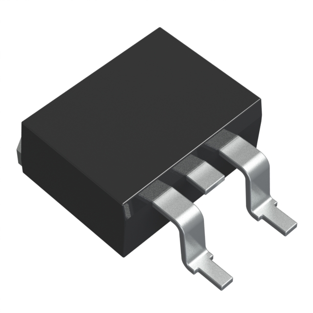
The STPR1620CG is a diode array rectifier manufactured by STMicroelectronics, configured as a 1 Pair Common Cathode design rated for 200 V DC reverse voltage and 8 A average rectified current per diode. The device is packaged in a Surface Mount TO-263-3 (D2PAK) configuration with 2 leads plus tab. This part is classified as Obsolete, necessitating identification of equivalent and substitute components for ongoing design requirements and procurement continuity.
Substiute Parts
Key Parameters
| Parameter | STPR1620CG Value |
|---|---|
| Diode Configuration | 1 Pair Common Cathode |
| Voltage - DC Reverse (Vr) (Max) | 200 V |
| Current - Average Rectified (Io) (per Diode) | 8 A |
| Voltage - Forward (Vf) (Max) @ If | 990 mV @ 8 A |
| Speed Classification | Fast Recovery ≤ 500 ns, > 200 mA (Io) |
| Reverse Recovery Time (trr) | 30 ns |
| Current - Reverse Leakage @ Vr | 50 µA @ 200 V |
| Operating Temperature - Junction (Max) | 150°C |
| Mounting Type | Surface Mount |
| Package / Case | TO-263-3, D2PAK (2 Leads + Tab), TO-263AB |
| Technology | Standard |
| RoHS Status | ROHS3 Compliant |
| Moisture Sensitivity Level (MSL) | 1 (Unlimited) |
Substitute Part Grouping Explanation
Substitution of the STPR1620CG is determined by the following critical parameters:
Primary Substitution Criteria:
- Diode Configuration: 1 Pair Common Cathode (mandatory match)
- Voltage - DC Reverse (Vr) (Max): 200 V (minimum requirement)
- Current - Average Rectified (Io) (per Diode): 8 A or greater (equal or higher rating acceptable)
- Package / Case: TO-263-3, D2PAK (2 Leads + Tab), TO-263AB (mechanical compatibility)
- Mounting Type: Surface Mount (assembly process compatibility)
Secondary Compatibility Parameters:
- Voltage - Forward (Vf) (Max): Acceptable within circuit design margins
- Reverse Recovery Time (trr): Fast Recovery classification maintained
- Operating Temperature - Junction: Minimum -65°C to 175°C range preferred for extended thermal performance
- RoHS Status: ROHS3 Compliant (regulatory requirement)
Substitute parts are grouped into two categories: Direct Equivalents (matching all primary criteria with identical or superior current ratings in D2PAK packaging) and Functional Alternatives (meeting electrical requirements with different current ratings or packaging formats for through-hole applications).
Parameter Comparison
| Part Number | Manufacturer | Vr (Max) | Io (per Diode) | Vf (Max) @ If | trr (ns) | Package | Mounting Type | Product Status | Technology |
|---|---|---|---|---|---|---|---|---|---|
| STPR1620CG | STMicroelectronics | 200 V | 8 A | 990 mV @ 8 A | 30 | TO-263-3, D2PAK | Surface Mount | Obsolete | Standard |
| FFB20UP20DN-F085 | onsemi | 200 V | 10 A | 1.15 V @ 10 A | 40 | TO-263-3, D2PAK | Surface Mount | Active | Standard |
| MUR1620CTG | onsemi | 200 V | 8 A | 975 mV @ 8 A | 35 | TO-220-3 | Through Hole | Active | Standard |
| SBR10200CTB-13-G | Diodes Incorporated | 200 V | 5 A | 920 mV @ 5 A | 20 | TO-263-3, D2PAK | Surface Mount | Active | Super Barrier |
| SBR10U200CTB | Diodes Incorporated | 200 V | 5 A | 820 mV @ 5 A | 30 | TO-263-3, D2PAK | Surface Mount | Obsolete | Super Barrier |
| SBR20A200CTB | Diodes Incorporated | 200 V | 10 A | 960 mV @ 20 A | 30 | TO-263-3, D2PAK | Surface Mount | Active | Super Barrier |
| SBR20A200CTB-13 | Diodes Incorporated | 200 V | 10 A | 960 mV @ 20 A | 30 | TO-263-3, D2PAK | Surface Mount | Active | Super Barrier |
| UGB10DCTHE3/81 | Vishay General Semiconductor - Diodes Division | 200 V | 5 A | 1.1 V @ 5 A | 25 | TO-263-3, D2PAK | Surface Mount | Active | Standard |
| VS-MURB1620CTRHM3 | Vishay General Semiconductor - Diodes Division | 200 V | 8 A | 975 mV @ 8 A | 20 | TO-263-3, D2PAK | Surface Mount | Active | Standard |
Engineering Selection Recommendations
Direct Equivalents (Recommended Primary Substitutes):
The following parts provide direct functional equivalence to the STPR1620CG with identical or superior electrical performance and maintain Surface Mount D2PAK packaging:
-
VS-MURB1620CTRHM3 (Vishay): Matches 8 A current rating and 200 V reverse voltage with identical D2PAK packaging. Active product status ensures long-term availability. Reverse recovery time of 20 ns provides improved switching performance. AEC-Q101 automotive qualification provides additional reliability assurance.
-
FFB20UP20DN-F085 (onsemi): Provides 10 A current rating (exceeds 8 A requirement) with 200 V reverse voltage in D2PAK packaging. Active product status with AEC-Q101 automotive qualification. Suitable for applications requiring higher current margin.
Higher Current Alternatives (D2PAK Surface Mount):
- SBR20A200CTB-13 and SBR20A200CTB (Diodes Incorporated): Both rated for 10 A in D2PAK packaging with 200 V reverse voltage. Active product status. Super Barrier technology provides lower forward voltage (960 mV @ 20 A). Tape & Reel and Tube packaging options available.
Lower Current Alternatives (D2PAK Surface Mount):
-
SBR10200CTB-13-G (Diodes Incorporated): Rated for 5 A in D2PAK packaging with 200 V reverse voltage. Active product status. Super Barrier technology with 20 ns reverse recovery time. Suitable for current-limited applications.
-
UGB10DCTHE3/81 (Vishay): Rated for 5 A in D2PAK packaging with 200 V reverse voltage. Active product status with AEC-Q101 automotive qualification. Standard technology with 25 ns reverse recovery time.
Through-Hole Alternative (Different Mounting Type):
- MUR1620CTG (onsemi): Matches 8 A current rating and 200 V reverse voltage with TO-220-3 through-hole packaging. Active product status. Suitable only for designs permitting through-hole assembly. SWITCHMODE™ series designation indicates optimized switching performance.
Obsolete Parts (Not Recommended for New Designs):
- SBR10U200CTB (Diodes Incorporated): Obsolete status; use SBR10200CTB-13-G as replacement.
All recommended substitutes maintain ROHS3 compliance and MSL 1 (Unlimited) moisture sensitivity rating, ensuring compatibility with standard manufacturing processes.
Frequently Asked Questions (FAQ)
Q: Can the STPR1620CG be directly replaced with FFB20UP20DN-F085?
A: Yes. Both devices share identical 200 V reverse voltage rating, 1 Pair Common Cathode configuration, and D2PAK Surface Mount packaging. FFB20UP20DN-F085 provides 10 A current rating, exceeding the 8 A requirement of STPR1620CG. Forward voltage characteristics are comparable within typical circuit design margins. FFB20UP20DN-F085 is Active status, ensuring procurement continuity.
Q: What is the difference between SBR20A200CTB and SBR20A200CTB-13?
A: Both parts are electrically identical with 10 A current rating, 200 V reverse voltage, and D2PAK packaging. The primary difference is packaging format: SBR20A200CTB is supplied in Tube packaging, while SBR20A200CTB-13 is supplied in Tape & Reel (TR) format. Selection depends on assembly line requirements and volume quantities.
Q: Why would I select a 5 A rated part (SBR10200CTB-13-G or UGB10DCTHE3/81) instead of an 8 A or 10 A rated part?
A: Lower current-rated parts are selected when circuit design specifications require reduced current handling or when thermal management constraints limit device dissipation. Super Barrier technology in SBR10200CTB-13-G provides lower forward voltage (920 mV @ 5 A) compared to standard technology, reducing power loss in current-limited applications. UGB10DCTHE3/81 offers AEC-Q101 automotive qualification for regulated applications.
Q: Is MUR1620CTG a suitable replacement for STPR1620CG?
A: MUR1620CTG provides electrical equivalence with identical 8 A current rating and 200 V reverse voltage. However, it uses TO-220-3 through-hole packaging instead of D2PAK Surface Mount. This substitution is only viable if the circuit board design and assembly process support through-hole mounting. MUR1620CTG is Active status with SWITCHMODE™ series optimization.
Q: What does "1 Pair Common Cathode" configuration mean for substitution purposes?
A: This configuration indicates the diode array contains two diodes sharing a common cathode terminal. Substitution requires identical configuration to maintain pin compatibility and circuit functionality. All listed substitute parts maintain this configuration.
Q: Are all substitute parts RoHS3 compliant?
A: Yes. All substitute parts listed maintain ROHS3 compliance, matching the regulatory status of STPR1620CG. This ensures compatibility with environmental and procurement requirements.
Q: What is the significance of AEC-Q101 qualification on certain substitute parts?
A: AEC-Q101 qualification indicates the part meets automotive industry reliability standards. Parts with this qualification (FFB20UP20DN-F085, UGB10DCTHE3/81, VS-MURB1620CTRHM3) are suitable for automotive and high-reliability applications requiring enhanced quality assurance and extended temperature performance.
Q: How do reverse recovery time differences affect part selection?
A: Reverse recovery time (trr) affects switching speed and electromagnetic interference characteristics. STPR1620CG specifies 30 ns. Substitute parts range from 20 ns (SBR10200CTB-13-G, VS-MURB1620CTRHM3) to 40 ns (FFB20UP20DN-F085). Lower trr values provide faster switching with reduced noise; higher values remain within Fast Recovery classification (≤ 500 ns) and are functionally compatible.
Q: Can I use a substitute part with higher forward voltage (Vf) rating?
A: Forward voltage differences must be evaluated within circuit design margins. STPR1620CG specifies 990 mV @ 8 A. Substitute parts range from 820 mV to 1.15 V depending on technology and current rating. Higher Vf increases power dissipation; lower Vf reduces dissipation. Circuit analysis is required to confirm compatibility with voltage regulation and thermal requirements.
Q: What is the difference between Standard and Super Barrier technology?
A: Super Barrier technology (used in SBR series parts) provides lower forward voltage and faster reverse recovery compared to Standard technology. This reduces power loss and improves switching efficiency. Selection depends on circuit efficiency requirements and thermal constraints.
Alternative Parts

SJ6012L2TP
Littelfuse Inc.
6 Alternative Parts

JMK107BBJ476MA-RE
Taiyo Yuden
10 Alternative Parts

GMK107BBJ475MA-T
Taiyo Yuden
5 Alternative Parts
SJ6020N2ARP
Littelfuse Inc.
3 Alternative Parts
SJ6025R2ATP
Littelfuse Inc.
4 Alternative Parts

2474-05L
API Delevan Inc.
1 Alternative Parts

4590R-684K
API Delevan Inc.
1 Alternative Parts

CM6560R-334
API Delevan Inc.
1 Alternative Parts

CM6460-104
API Delevan Inc.
1 Alternative Parts

5526-12
API Delevan Inc.
1 Alternative Parts