


Request Quote
(Ships tomorrow)
STP80NF55L-06 Equivalent & Substitute Parts
Part Overview
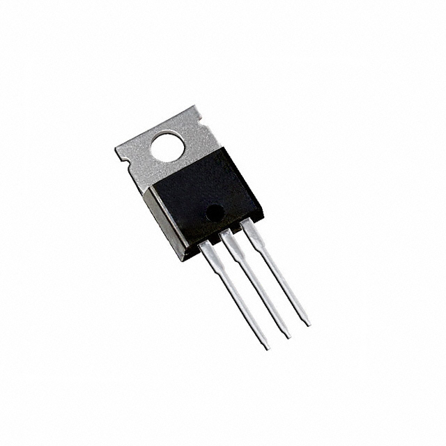
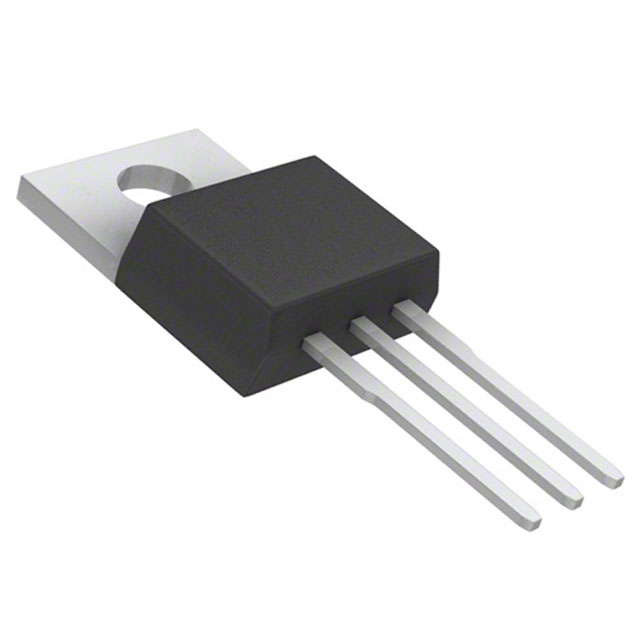
The STP80NF55L-06 is an N-Channel MOSFET manufactured by STMicroelectronics, rated for 55V drain-to-source voltage and 80A continuous drain current at 25°C. This device is housed in a TO-220-3 through-hole package and is part of the STripFET™ II series. The component is classified as obsolete, necessitating identification of equivalent and substitute parts for ongoing design requirements and procurement needs. Substitute parts must maintain electrical compatibility within the specified parameter ranges while meeting current product availability and compliance standards.
Substiute Parts
Key Parameters
| Parameter | STP80NF55L-06 | Unit |
|---|---|---|
| FET Type | N-Channel | — |
| Drain to Source Voltage (Vdss) | 55 | V |
| Current - Continuous Drain (Id) @ 25°C | 80 | A (Tc) |
| Rds On (Max) @ Id, Vgs | 6.5 | mOhm @ 40A, 10V |
| Gate Charge (Qg) (Max) @ Vgs | 136 | nC @ 5V |
| Vgs(th) (Max) @ Id | 1 | V @ 250µA |
| Vgs (Max) | ±16 | V |
| Input Capacitance (Ciss) (Max) @ Vds | 4850 | pF @ 25V |
| Power Dissipation (Max) | 300 | W (Tc) |
| Operating Temperature | -55 to 175 | °C (TJ) |
| Mounting Type | Through Hole | — |
| Package / Case | TO-220-3 | — |
| Technology | MOSFET (Metal Oxide) | — |
| RoHS Status | ROHS3 Compliant | — |
Substitute Part Grouping Explanation
Substitution of the STP80NF55L-06 is determined by the following critical electrical and mechanical parameters:
Primary Substitution Criteria:
- FET Type: N-Channel (mandatory match)
- Drain to Source Voltage (Vdss): 55V or higher (equal or greater rating required)
- Continuous Drain Current (Id) @ 25°C: 80A or higher (equal or greater rating required)
- Package / Case: TO-220-3 (mechanical compatibility)
- Mounting Type: Through Hole (mechanical compatibility)
- Operating Temperature Range: -55°C to 175°C (must encompass or match)
- Technology: MOSFET (Metal Oxide) (functional equivalence)
Secondary Compatibility Parameters:
- Rds On (Max): Lower or equal values indicate improved performance
- Gate Charge (Qg): Lower values reduce switching losses
- Input Capacitance (Ciss): Lower values reduce gate drive requirements
- Power Dissipation (Max): Higher values provide thermal margin
- Vgs (Max): ±20V or higher accommodates standard gate drive circuits
- RoHS3 Compliance: Required for regulatory alignment
Substitute parts are grouped into two categories: Direct Substitutes (matching all primary criteria with active product status) and Similar Substitutes (meeting electrical requirements with variations in secondary parameters or product status).
Parameter Comparison
| Parameter | STP80NF55L-06 | IRF1010EZPBF | AOT2606L | AUIRF3205 | AUIRF3205Z | AUIRF3305 | FDP070AN06A0 | HUF75344P3 | HUF75345P3 | IRF1018EPBF | IRF1104PBF | Unit |
|---|---|---|---|---|---|---|---|---|---|---|---|---|
| FET Type | N-Channel | N-Channel | N-Channel | N-Channel | N-Channel | N-Channel | N-Channel | N-Channel | N-Channel | N-Channel | N-Channel | — |
| Drain to Source Voltage (Vdss) | 55 | 60 | 60 | 55 | 55 | 55 | 60 | 55 | 55 | 60 | 40 | V |
| Current - Continuous Drain (Id) @ 25°C | 80 | 75 | 72 | 75 | 75 | 140 | 80 | 75 | 75 | 79 | 100 | A (Tc) |
| Rds On (Max) @ Id, Vgs | 6.5 @ 40A, 10V | 8.5 @ 51A, 10V | 6.5 @ 20A, 10V | 8 @ 62A, 10V | 6.5 @ 66A, 10V | 8 @ 75A, 10V | 7 @ 80A, 10V | 8 @ 75A, 10V | 7 @ 75A, 10V | 8.4 @ 47A, 10V | 9 @ 60A, 10V | mOhm |
| Gate Charge (Qg) (Max) @ Vgs | 136 @ 5V | 86 @ 10V | 75 @ 10V | 146 @ 10V | 110 @ 10V | 150 @ 10V | 66 @ 10V | 210 @ 20V | 275 @ 20V | 69 @ 10V | 93 @ 10V | nC |
| Vgs(th) (Max) @ Id | 1 @ 250µA | 4 @ 100µA | 3.5 @ 250µA | 4 @ 250µA | 4 @ 250µA | 4 @ 250µA | 4 @ 250µA | 4 @ 250µA | 4 @ 250µA | 4 @ 100µA | 4 @ 250µA | V |
| Vgs (Max) | ±16 | ±20 | ±20 | ±20 | ±20 | ±20 | ±20 | ±20 | ±20 | ±20 | ±20 | V |
| Input Capacitance (Ciss) (Max) @ Vds | 4850 @ 25V | 2810 @ 25V | 4050 @ 30V | 3247 @ 25V | 3450 @ 25V | 3650 @ 25V | 3000 @ 25V | 3200 @ 25V | 4000 @ 25V | 2290 @ 50V | 2900 @ 25V | pF |
| Power Dissipation (Max) | 300 | 140 | 115 | 200 | 170 | 330 | 175 | 285 | 325 | 110 | 170 | W (Tc) |
| Operating Temperature | -55 to 175 | -55 to 175 | -55 to 175 | -55 to 175 | -55 to 175 | -55 to 175 | -55 to 175 | -55 to 175 | -55 to 175 | -55 to 175 | -55 to 175 | °C (TJ) |
| Mounting Type | Through Hole | Through Hole | Through Hole | Through Hole | Through Hole | Through Hole | Through Hole | Through Hole | Through Hole | Through Hole | Through Hole | — |
| Package / Case | TO-220-3 | TO-220-3 | TO-220-3 | TO-220-3 | TO-220-3 | TO-220-3 | TO-220-3 | TO-220-3 | TO-220-3 | TO-220-3 | TO-220-3 | — |
| Technology | MOSFET (Metal Oxide) | MOSFET (Metal Oxide) | MOSFET (Metal Oxide) | MOSFET (Metal Oxide) | MOSFET (Metal Oxide) | MOSFET (Metal Oxide) | MOSFET (Metal Oxide) | MOSFET (Metal Oxide) | MOSFET (Metal Oxide) | MOSFET (Metal Oxide) | MOSFET (Metal Oxide) | — |
| RoHS Status | ROHS3 Compliant | ROHS3 Compliant | ROHS3 Compliant | Not Specified | ROHS3 Compliant | ROHS3 Compliant | Not Specified | ROHS3 Compliant | ROHS3 Compliant | ROHS3 Compliant | ROHS3 Compliant | — |
Engineering Selection Recommendations
Direct Substitutes (Active Product Status):
The following parts are recommended as direct substitutes based on active product status, full compliance with primary electrical parameters, and RoHS3 certification:
-
FDP070AN06A0 (Fairchild Semiconductor): Matches 80A continuous drain current at 55V or higher (60V rating), TO-220-3 package, active product status. Rds On of 7 mOhm provides acceptable performance margin. Gate charge of 66 nC is lower than the original, reducing switching losses.
-
HUF75344P3 (onsemi): Rated for 75A at 55V with TO-220-3 package and active product status. Rds On of 8 mOhm is slightly higher than the original. Power dissipation of 285W exceeds the original 300W specification. UltraFET™ series provides established reliability.
-
HUF75345P3 (onsemi): Rated for 75A at 55V with TO-220-3 package and active product status. Rds On of 7 mOhm matches the original performance. Power dissipation of 325W provides thermal margin above the original 300W. UltraFET™ series provides established reliability.
Similar Substitutes (Electrical Compatibility with Status Considerations):
The following parts meet electrical substitution criteria but have product status or compliance considerations:
-
AUIRF3205Z (Infineon Technologies): Rated for 75A at 55V with TO-220-3 package and RoHS3 compliance. Product status is "Not For New Designs," limiting suitability for new applications. Rds On of 6.5 mOhm at 66A provides superior performance. Suitable for legacy system maintenance only.
-
AUIRF3305 (Infineon Technologies): Rated for 140A at 55V with TO-220-3 package and RoHS3 compliance. Product status is obsolete, similar to the original part. Provides higher current capability (140A) and power dissipation (330W) for applications requiring increased thermal margin.
-
IRF1010EZPBF (Infineon Technologies): Rated for 75A at 60V with TO-220-3 package and RoHS3 compliance. Active product status. Vdss of 60V exceeds the 55V requirement. Gate charge of 86 nC is lower than the original, reducing switching losses. Power dissipation of 140W is lower than the original 300W.
-
IRF1018EPBF (Infineon Technologies): Rated for 79A at 60V with TO-220-3 package and RoHS3 compliance. Active product status. Vdss of 60V exceeds the 55V requirement. Gate charge of 69 nC is significantly lower than the original. Power dissipation of 110W is lower than the original 300W.
-
IRF1104PBF (Infineon Technologies): Rated for 100A at 40V with TO-220-3 package and RoHS3 compliance. Active product status. Vdss of 40V is below the 55V requirement and is not suitable for direct substitution in applications requiring 55V rating.
-
AOT2606L (Alpha & Omega Semiconductor Inc.): Rated for 72A at 60V with TO-220-3 package and RoHS3 compliance. Active product status. Vdss of 60V exceeds the 55V requirement. Rds On of 6.5 mOhm at 20A matches the original performance specification.
-
AUIRF3205 (International Rectifier): Rated for 75A at 55V with TO-220-3 package. Active product status. RoHS status not specified. Rds On of 8 mOhm at 62A provides acceptable performance. Power dissipation of 200W is lower than the original 300W.
Frequently Asked Questions (FAQ)
Q: Can I use a substitute part with a higher Vdss rating than the original STP80NF55L-06?
A: Yes. A higher Vdss rating (such as 60V) is acceptable and provides additional voltage margin. The substitute part will operate safely in circuits designed for 55V operation. However, the circuit design must still respect the original 55V maximum operating voltage.
Q: What is the significance of the continuous drain current (Id) rating?
A: The continuous drain current rating specifies the maximum current the MOSFET can conduct continuously at 25°C case temperature without exceeding thermal limits. Substitute parts must have an Id rating equal to or greater than 80A to handle the same current levels as the original STP80NF55L-06.
Q: Why do some substitute parts have lower power dissipation ratings than the original?
A: Power dissipation depends on die size, thermal design, and package efficiency. Lower power dissipation ratings indicate the part generates less heat at the same current levels, which is generally beneficial. However, if your application requires the full 300W dissipation capability, select a substitute with equal or higher power dissipation rating.
Q: Is the TO-220-3 package compatible with all listed substitutes?
A: Yes. All listed substitute parts use the TO-220-3 through-hole package, ensuring mechanical and pin compatibility with the original STP80NF55L-06. Direct PCB mounting and heatsink attachment are identical.
Q: What does "Not For New Designs" product status mean?
A: Parts with "Not For New Designs" status are still available but manufacturers recommend against using them in new circuit designs. These parts are suitable for replacement in existing systems or legacy applications. For new designs, select parts with "Active" product status.
Q: Why is RoHS3 compliance important?
A: RoHS3 compliance ensures the part meets environmental and regulatory requirements for hazardous substance restrictions. All recommended direct substitutes carry RoHS3 certification, maintaining regulatory alignment with the original part.
Q: How does gate charge (Qg) affect circuit performance?
A: Gate charge determines the energy required to switch the MOSFET on and off. Lower gate charge values reduce switching losses and allow faster switching speeds with lower gate drive power requirements. Substitute parts with lower Qg values (such as IRF1018EPBF at 69 nC) improve overall circuit efficiency.
Q: Can I substitute a part with lower Rds On (on-resistance)?
A: Yes. Lower Rds On values are beneficial as they reduce conduction losses and heat generation. Substitute parts with Rds On equal to or lower than the original 6.5 mOhm will improve circuit efficiency and thermal performance.
Q: What is the difference between Ta and Tc temperature ratings?
A: Ta refers to ambient temperature, while Tc refers to case temperature. Continuous drain current ratings are typically specified at Tc (case temperature). All listed parts operate across the same temperature range (-55°C to 175°C junction temperature), ensuring thermal compatibility.
Q: Are there any gate voltage (Vgs) compatibility concerns?
A: The original STP80NF55L-06 has a maximum Vgs of ±16V. Most substitute parts have ±20V ratings, which is compatible and provides additional margin. Standard gate drive circuits operating at ±10V or ±15V will function correctly with all listed substitutes.
Alternative Parts

SJ6012L2TP
Littelfuse Inc.
6 Alternative Parts

JMK107BBJ476MA-RE
Taiyo Yuden
10 Alternative Parts

GMK107BBJ475MA-T
Taiyo Yuden
5 Alternative Parts
SJ6020N2ARP
Littelfuse Inc.
3 Alternative Parts
SJ6025R2ATP
Littelfuse Inc.
4 Alternative Parts

2474-05L
API Delevan Inc.
1 Alternative Parts

4590R-684K
API Delevan Inc.
1 Alternative Parts

CM6560R-334
API Delevan Inc.
1 Alternative Parts

CM6460-104
API Delevan Inc.
1 Alternative Parts

5526-12
API Delevan Inc.
1 Alternative Parts