


Request Quote
(Ships tomorrow)
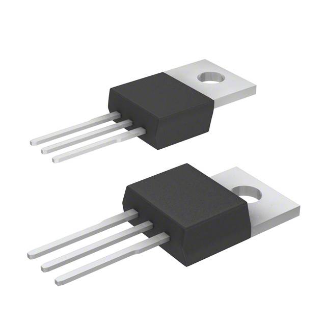
STP7NM80 N-Channel 800V MOSFET Equivalent & Substitute Parts
Part Overview
The STP7NM80 is an N-Channel 800V 6.5A MOSFET manufactured by STMicroelectronics in the MDmesh™ series, housed in a TO-220-3 through-hole package. This device is classified as obsolete, necessitating identification of equivalent and substitute components for ongoing design support and procurement. The part operates across a temperature range of -55°C to 150°C and dissipates up to 90W at the case temperature. Substitute parts must maintain electrical compatibility across drain-source voltage, continuous drain current, gate charge characteristics, and thermal performance parameters while accommodating the through-hole TO-220-3 package format.
Substiute Parts
Key Parameters
| Parameter | Value | Unit |
|---|---|---|
| Drain to Source Voltage (Vdss) | 800 | V |
| Continuous Drain Current (Id) @ 25°C | 6.5 | A |
| On-State Resistance (Rds On Max) @ Id, Vgs | 1.05 Ohm @ 3.25A, 10V | Ohm |
| Gate Threshold Voltage (Vgs(th) Max) @ Id | 5 | V @ 250µA |
| Gate Charge (Qg Max) @ Vgs | 18 | nC @ 10V |
| Maximum Gate Voltage (Vgs Max) | ±30 | V |
| Input Capacitance (Ciss Max) @ Vds | 620 | pF @ 25V |
| Power Dissipation (Max) | 90 | W |
| Operating Temperature Range | -55 to 150 | °C |
| Package Type | TO-220-3 | Through Hole |
| RoHS Status | ROHS3 Compliant |
Substitute Part Grouping Explanation
Substitution eligibility for the STP7NM80 is determined by strict adherence to the following electrical and mechanical parameters:
Primary Substitution Criteria:
- Drain to Source Voltage (Vdss): Must equal 800V
- Package Type: Must be TO-220-3 through-hole configuration
- FET Type: Must be N-Channel Metal Oxide MOSFET
- Operating Temperature Range: Must support -55°C to 150°C minimum
- Gate Voltage Rating (Vgs Max): Must support ±30V or greater
- RoHS3 Compliance: Required for regulatory alignment
Secondary Compatibility Parameters:
- Continuous Drain Current (Id): Substitute parts rated at 4A or higher are acceptable for applications requiring 6.5A nominal operation
- On-State Resistance (Rds On): Lower values indicate improved performance; values up to 1.44 Ohm are within acceptable substitution range
- Gate Charge (Qg): Values between 18nC and 41nC maintain switching characteristic compatibility
- Input Capacitance (Ciss): Values up to 2050pF are acceptable for circuit integration
All four substitute parts meet the primary criteria. Substitution selection depends on application-specific requirements for current handling, power dissipation, and switching speed.
Parameter Comparison
| Parameter | STP7NM80 (Main) | SPP04N80C3XKSA1 | SPP06N80C3XKSA1 | IXFP7N80P | IXFP10N80P |
|---|---|---|---|---|---|
| Manufacturer | STMicroelectronics | Infineon Technologies | Infineon Technologies | IXYS | IXYS |
| Vdss (V) | 800 | 800 | 800 | 800 | 800 |
| Id @ 25°C (A) | 6.5 | 4 | 6 | 7 | 10 |
| Rds On Max (Ohm) | 1.05 @ 3.25A, 10V | 1.3 @ 2.5A, 10V | 0.9 @ 3.8A, 10V | 1.44 @ 3.5A, 10V | 1.1 @ 5A, 10V |
| Vgs(th) Max (V) | 5 @ 250µA | 3.9 @ 240µA | 3.9 @ 250µA | 5 @ 1mA | 5.5 @ 2.5mA |
| Qg Max (nC) | 18 @ 10V | 31 @ 10V | 41 @ 10V | 32 @ 10V | 40 @ 10V |
| Vgs Max (V) | ±30 | ±20 | ±20 | ±30 | ±30 |
| Ciss Max (pF) | 620 @ 25V | 570 @ 100V | 785 @ 100V | 1890 @ 25V | 2050 @ 25V |
| Power Dissipation Max (W) | 90 | 63 | 83 | 200 | 300 |
| Operating Temperature (°C) | -55 to 150 | -55 to 150 | -55 to 150 | -55 to 150 | -55 to 150 |
| Package | TO-220-3 | TO-220-3 | TO-220-3 | TO-220-3 | TO-220-3 |
| Product Status | Obsolete | Active | Active | Active | Active |
| RoHS3 Compliance | Yes | Yes | Yes | Yes | Yes |
Engineering Selection Recommendations
SPP06N80C3XKSA1 (Infineon CoolMOS™)
This substitute provides the closest electrical match to the STP7NM80. The 6A continuous drain current rating aligns with the original 6.5A specification, and the 0.9 Ohm on-state resistance offers superior performance. The 83W power dissipation rating accommodates the original 90W specification. This part is actively manufactured and maintains full RoHS3 compliance. The lower gate threshold voltage (3.9V) and reduced gate charge (41nC) improve switching efficiency. Note: Vgs Max is ±20V, which is lower than the original ±30V specification; verify gate drive circuit compatibility.
IXFP7N80P (IXYS HiPerFET™)
This substitute matches the original 6.5A current requirement with a 7A rating and provides 200W power dissipation capability. The 1.44 Ohm on-state resistance is acceptable for most applications. Gate threshold voltage (5V @ 1mA) and maximum gate voltage (±30V) align with the original specifications. Higher input capacitance (1890pF) may require gate drive circuit adjustment. This part is actively manufactured with full RoHS3 compliance.
IXFP10N80P (IXYS HiPerFET™)
This substitute provides enhanced current handling at 10A continuous drain current and 300W power dissipation, suitable for applications requiring higher performance margins. The 1.1 Ohm on-state resistance and ±30V gate voltage rating maintain compatibility with the original design. Higher gate charge (40nC) and input capacitance (2050pF) require verification against gate drive circuit specifications. This part is actively manufactured with full RoHS3 compliance.
SPP04N80C3XKSA1 (Infineon CoolMOS™)
This substitute is suitable only for applications where the 4A continuous drain current rating is sufficient. The 63W power dissipation is below the original 90W specification. The 1.3 Ohm on-state resistance and lower gate charge (31nC) provide switching advantages. This part is actively manufactured with full RoHS3 compliance. Vgs Max is ±20V; verify gate drive circuit compatibility.
Frequently Asked Questions (FAQ)
Q: Can the SPP06N80C3XKSA1 directly replace the STP7NM80 in all applications?
A: The SPP06N80C3XKSA1 is electrically compatible for most applications. However, the gate voltage rating is ±20V compared to the original ±30V. Verify that your gate drive circuit operates within ±20V limits. The lower on-state resistance (0.9 Ohm vs. 1.05 Ohm) and reduced power dissipation (83W vs. 90W) are advantageous. Pin configuration and TO-220-3 package are identical.
Q: What is the difference between the IXYS HiPerFET™ parts (IXFP7N80P and IXFP10N80P)?
A: Both parts share the same 800V drain-source voltage and TO-220-3 package. The IXFP7N80P is rated for 7A continuous current with 200W dissipation, while the IXFP10N80P is rated for 10A with 300W dissipation. The IXFP10N80P has higher gate charge (40nC vs. 32nC) and input capacitance (2050pF vs. 1890pF), requiring stronger gate drive capability. Select based on your application's current and thermal requirements.
Q: Are all substitute parts RoHS3 compliant?
A: Yes. All four substitute parts (SPP04N80C3XKSA1, SPP06N80C3XKSA1, IXFP7N80P, and IXFP10N80P) are RoHS3 compliant and REACH unaffected, matching the original STP7NM80 compliance status.
Q: Can I use the SPP04N80C3XKSA1 if my application requires 6.5A continuous current?
A: No. The SPP04N80C3XKSA1 is rated for 4A continuous drain current, which is insufficient for applications requiring 6.5A. Use SPP06N80C3XKSA1, IXFP7N80P, or IXFP10N80P instead.
Q: What is the impact of higher input capacitance in the IXYS parts?
A: The IXFP7N80P (1890pF) and IXFP10N80P (2050pF) have significantly higher input capacitance compared to the STP7NM80 (620pF). This increases gate charge requirements and may necessitate gate drive circuit modifications to maintain switching speed and efficiency. Verify that your gate driver can supply the required current for the specified switching frequency.
Q: Are the Infineon CoolMOS™ parts (SPP04N80C3XKSA1 and SPP06N80C3XKSA1) pin-compatible with the STP7NM80?
A: Yes. Both Infineon parts use the standard TO-220-3 package with identical pin configuration (Gate, Drain, Source). Physical mounting and PCB layout are directly compatible.
Q: What is the significance of the lower gate threshold voltage in the Infineon parts?
A: The Infineon CoolMOS™ parts have Vgs(th) of 3.9V compared to the STP7NM80's 5V. This lower threshold voltage allows faster turn-on at lower gate drive voltages, improving switching speed and reducing gate drive power consumption. Ensure your gate drive circuit can reliably distinguish between logic low and high states at these lower thresholds.
Q: Can I use multiple substitute parts interchangeably in the same design?
A: No. Each substitute part has different electrical characteristics (Rds On, Qg, Ciss, power dissipation). Select one substitute based on your specific application requirements and verify circuit performance. Mixing different parts in the same design may result in unbalanced current sharing and thermal stress.
Alternative Parts

SJ6012L2TP
Littelfuse Inc.
6 Alternative Parts

JMK107BBJ476MA-RE
Taiyo Yuden
10 Alternative Parts

GMK107BBJ475MA-T
Taiyo Yuden
5 Alternative Parts
SJ6020N2ARP
Littelfuse Inc.
3 Alternative Parts
SJ6025R2ATP
Littelfuse Inc.
4 Alternative Parts

2474-05L
API Delevan Inc.
1 Alternative Parts

4590R-684K
API Delevan Inc.
1 Alternative Parts

CM6560R-334
API Delevan Inc.
1 Alternative Parts

CM6460-104
API Delevan Inc.
1 Alternative Parts

5526-12
API Delevan Inc.
1 Alternative Parts