


Request Quote
(Ships tomorrow)
STP5NK90Z Equivalent & Substitute Parts
Part Overview
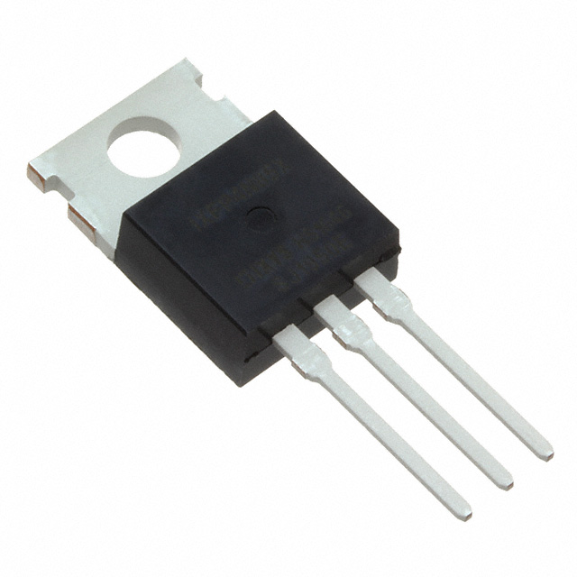
The STP5NK90Z is an N-Channel MOSFET manufactured by STMicroelectronics, rated for 900V drain-to-source voltage with 4.5A continuous drain current at 25°C. This device is packaged in TO-220AB through-hole configuration and is part of the SuperMESH™ series. The product status is obsolete, making equivalent and substitute parts necessary for ongoing design support and procurement.
Substiute Parts
Key Parameters
| Parameter | Value | Unit |
|---|---|---|
| Drain to Source Voltage (Vdss) | 900 | V |
| Continuous Drain Current (Id) @ 25°C | 4.5 | A |
| Rds On (Max) @ Id, Vgs | 2.5 | Ohm @ 2.25A, 10V |
| Gate Charge (Qg) (Max) @ Vgs | 41.5 | nC @ 10V |
| Input Capacitance (Ciss) (Max) @ Vds | 1160 | pF @ 25V |
| Power Dissipation (Max) | 125 | W |
| Operating Temperature Range | -55 to 150 | °C |
| Package Type | TO-220-3 | Through Hole |
| Vgs (Max) | ±30 | V |
Substitute Part Grouping Explanation
Substitution of the STP5NK90Z is determined by the following critical parameters:
Voltage Rating Compatibility: The drain-to-source voltage (Vdss) must equal or exceed 900V to maintain circuit protection margins in high-voltage applications.
Current Rating Compatibility: The continuous drain current (Id) must equal or exceed 4.5A to support the same load conditions without thermal stress.
On-State Resistance (Rds On): The maximum on-state resistance must not exceed 2.5Ohm at the specified gate-source voltage to maintain equivalent power dissipation characteristics.
Gate Charge (Qg): Gate charge affects switching speed and driver requirements. Substitutes with significantly lower gate charge may alter circuit timing.
Input Capacitance (Ciss): Input capacitance influences gate drive circuit design and switching losses.
Package and Mounting: All substitutes must use TO-220 through-hole packaging to ensure mechanical and thermal compatibility.
Operating Temperature Range: All substitutes must support the -55°C to 150°C operating range.
Compliance Status: RoHS3 compliance and REACH unaffected status are preferred for modern applications.
Parameter Comparison
| Parameter | STP5NK90Z | FQP6N80C | IRFBF30 | IRFBF30PBF | IXFP4N85X |
|---|---|---|---|---|---|
| Manufacturer | STMicroelectronics | onsemi | Vishay Siliconix | Vishay Siliconix | IXYS |
| Vdss (V) | 900 | 800 | 900 | 900 | 850 |
| Id @ 25°C (A) | 4.5 | 5.5 | 3.6 | 3.6 | 3.5 |
| Rds On (Max) @ 10V (Ohm) | 2.5 | 2.5 | 3.7 | 3.7 | 2.5 |
| Qg (Max) @ 10V (nC) | 41.5 | 30 | 78 | 78 | 7 |
| Ciss (Max) @ 25V (pF) | 1160 | 1310 | 1200 | 1200 | 247 |
| Power Dissipation (Max) (W) | 125 | 158 | 125 | 125 | 150 |
| Operating Temperature (°C) | -55 to 150 | -55 to 150 | -55 to 150 | -55 to 150 | -55 to 150 |
| Package | TO-220-3 | TO-220-3 | TO-220-3 | TO-220-3 | TO-220-3 |
| Vgs (Max) (V) | ±30 | ±30 | ±20 | ±20 | ±30 |
| Product Status | Obsolete | Active | Active | Active | Active |
| RoHS Status | ROHS3 Compliant | ROHS3 Compliant | RoHS Non-Compliant | ROHS3 Compliant | ROHS3 Compliant |
Engineering Selection Recommendations
Primary Substitute: IRFBF30PBF
The IRFBF30PBF is the most direct equivalent to the STP5NK90Z. Both devices share identical voltage ratings (900V Vdss), equivalent on-state resistance (2.5Ohm at 10V), matching power dissipation (125W), and identical operating temperature range (-55°C to 150°C). The IRFBF30PBF is actively manufactured, ROHS3 compliant, and available in high inventory (15,411 pieces). The primary trade-off is lower continuous drain current (3.6A versus 4.5A), which is acceptable for applications not requiring the full 4.5A rating.
Secondary Substitute: IXFP4N85X
The IXFP4N85X offers superior switching characteristics with significantly lower gate charge (7nC versus 41.5nC) and input capacitance (247pF versus 1160pF). This device maintains equivalent on-state resistance (2.5Ohm at 10V) and higher power dissipation capability (150W). The voltage rating is reduced to 850V, which is acceptable for applications with design margins below 900V. This device is actively manufactured, ROHS3 compliant, and widely available (18,350 pieces).
Alternative Substitute: FQP6N80C
The FQP6N80C provides higher continuous drain current (5.5A) and improved power dissipation (158W) compared to the STP5NK90Z. On-state resistance matches at 2.5Ohm. The voltage rating is reduced to 800V, limiting use to applications with adequate design margins. Gate charge is lower (30nC), reducing driver requirements. This device is actively manufactured, ROHS3 compliant, and available in high inventory (16,162 pieces).
Not Recommended: IRFBF30
The IRFBF30 is electrically equivalent to IRFBF30PBF but carries RoHS non-compliant status, making it unsuitable for modern applications subject to environmental regulations.
Frequently Asked Questions (FAQ)
Q: Can the FQP6N80C replace the STP5NK90Z in all applications?
A: The FQP6N80C is suitable for applications where the circuit operates below 800V. The reduced voltage rating (800V versus 900V) eliminates the 100V design margin present in the original STP5NK90Z. Applications requiring the full 900V rating must use IRFBF30PBF or IXFP4N85X.
Q: What is the impact of lower gate charge in the IXFP4N85X?
A: Lower gate charge (7nC versus 41.5nC) reduces the charge that must be supplied by the gate driver circuit, resulting in faster switching transitions and lower gate drive power dissipation. Gate driver circuits designed for the STP5NK90Z will operate with improved performance margins when driving the IXFP4N85X.
Q: Are all substitute parts available in the same packaging?
A: All substitute parts use TO-220-3 through-hole packaging, ensuring mechanical and thermal compatibility. Mounting footprints and heatsink interfaces are identical.
Q: Which substitute offers the best thermal performance?
A: The FQP6N80C provides the highest power dissipation rating (158W), followed by IXFP4N85X (150W). Both exceed the STP5NK90Z rating (125W). Thermal performance also depends on heatsink design and ambient conditions.
Q: Is the IRFBF30PBF suitable for new designs?
A: Yes. The IRFBF30PBF is actively manufactured, ROHS3 compliant, and REACH unaffected. It is suitable for new designs requiring 900V voltage rating and equivalent electrical characteristics to the obsolete STP5NK90Z.
Q: What is the significance of the ±20V maximum gate-source voltage in IRFBF30 and IRFBF30PBF?
A: The ±20V Vgs(Max) rating is lower than the STP5NK90Z (±30V). Gate driver circuits must limit gate voltage to ±20V maximum. Most standard gate driver circuits operate within this range, but circuits designed to exploit the full ±30V range of the STP5NK90Z require modification.
Q: Can multiple substitute parts be used interchangeably in the same circuit?
A: No. Each substitute part has different electrical characteristics. Circuit redesign and validation are required when changing from one substitute to another. Differences in gate charge, input capacitance, and on-state resistance affect gate driver performance and switching losses.
Alternative Parts

SJ6012L2TP
Littelfuse Inc.
6 Alternative Parts

JMK107BBJ476MA-RE
Taiyo Yuden
10 Alternative Parts

GMK107BBJ475MA-T
Taiyo Yuden
5 Alternative Parts
SJ6020N2ARP
Littelfuse Inc.
3 Alternative Parts
SJ6025R2ATP
Littelfuse Inc.
4 Alternative Parts

2474-05L
API Delevan Inc.
1 Alternative Parts

4590R-684K
API Delevan Inc.
1 Alternative Parts

CM6560R-334
API Delevan Inc.
1 Alternative Parts

CM6460-104
API Delevan Inc.
1 Alternative Parts

5526-12
API Delevan Inc.
1 Alternative Parts