


Request Quote
(Ships tomorrow)
STP45N10F7 Equivalent & Substitute Parts
Part Overview
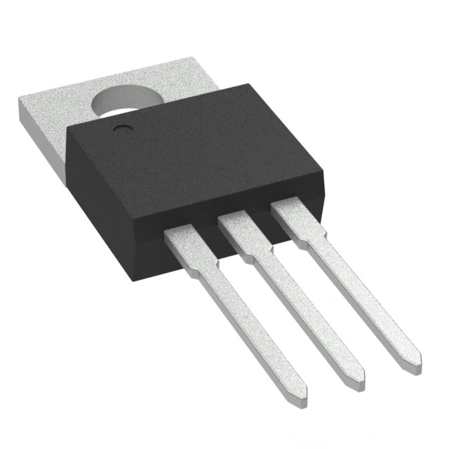
The STP45N10F7 is an N-Channel MOSFET manufactured by STMicroelectronics, rated for 100V drain-to-source voltage with 45A continuous drain current at 25°C. This device is housed in a TO-220-3 through-hole package and is part of the DeepGATE™ and STripFET™ VII series. The component is currently in active production status with RoHS3 compliance and REACH unaffected designation.
Equivalent and substitute parts are identified when applications require alternative sourcing due to inventory constraints, supply chain considerations, or when design specifications allow for components with enhanced electrical performance within the same voltage and package class.
Substiute Parts
Key Parameters
| Parameter | Value | Unit |
|---|---|---|
| Drain to Source Voltage (Vdss) | 100 | V |
| Continuous Drain Current (Id) @ 25°C | 45 | A |
| On-State Resistance (Rds On) @ 22.5A, 10V | 18 | mOhm |
| Gate Threshold Voltage (Vgs(th)) @ 250µA | 4.5 | V |
| Gate Charge (Qg) @ 10V | 25 | nC |
| Power Dissipation (Max) | 60 | W |
| Operating Temperature Range | -55 to 175 | °C |
| Package Type | TO-220-3 | — |
| Mounting Type | Through Hole | — |
Substitute Part Grouping Explanation
Substitute parts for the STP45N10F7 are qualified based on the following electrical and mechanical criteria:
Primary Substitution Criteria:
- Drain-to-Source Voltage (Vdss): 100V (exact match required)
- Package Type: TO-220-3 through-hole configuration (mechanical compatibility)
- FET Type: N-Channel MOSFET (functional equivalence)
- Technology: Metal Oxide Semiconductor (process compatibility)
- Operating Temperature Range: -55°C to 175°C (thermal envelope match)
- RoHS3 Compliance and REACH Unaffected status (regulatory alignment)
Secondary Performance Parameters (allowable variation):
- Continuous Drain Current (Id): 45A or greater
- On-State Resistance (Rds On): 18mOhm or lower (lower resistance indicates improved performance)
- Gate Charge (Qg): 25nC or lower (lower gate charge indicates faster switching)
- Power Dissipation: 60W or greater (higher dissipation capability provides design margin)
All substitute parts listed maintain the 100V voltage rating and TO-220-3 package specification, ensuring direct mechanical and electrical compatibility with the STP45N10F7 in standard applications.
Parameter Comparison
| Parameter | STP45N10F7 (STMicroelectronics) | CSD19534KCS (Texas Instruments) | IRF3710ZPBF (Infineon) | IXTP60N10T (IXYS) | IXTP75N10P (IXYS) |
|---|---|---|---|---|---|
| Drain to Source Voltage (Vdss) | 100V | 100V | 100V | 100V | 100V |
| Continuous Drain Current (Id) @ 25°C | 45A (Tc) | 100A (Ta) | 59A (Tc) | 60A (Tc) | 75A (Tc) |
| On-State Resistance (Rds On) @ 10V | 18mOhm @ 22.5A | 16.5mOhm @ 30A | 18mOhm @ 35A | 18mOhm @ 25A | 25mOhm @ 500mA |
| Gate Threshold Voltage (Vgs(th)) @ 250µA | 4.5V | 3.4V | 4V | 4.5V | 5.5V |
| Gate Charge (Qg) @ 10V | 25nC | 22.2nC | 120nC | 49nC | 74nC |
| Power Dissipation (Max) | 60W (Tc) | 118W (Tc) | 160W (Tc) | 176W (Tc) | 360W (Tc) |
| Operating Temperature Range | -55°C to 175°C | -55°C to 175°C | -55°C to 175°C | -55°C to 175°C | -55°C to 175°C |
| Package Type | TO-220-3 | TO-220-3 | TO-220-3 | TO-220-3 | TO-220-3 |
| Mounting Type | Through Hole | Through Hole | Through Hole | Through Hole | Through Hole |
| RoHS3 Compliance | Yes | Yes | Yes | Yes | Yes |
| REACH Status | Unaffected | Unaffected | Unaffected | Unaffected | Unaffected |
Engineering Selection Recommendations
CSD19534KCS (Texas Instruments)
The CSD19534KCS qualifies as a direct substitute with enhanced current handling capability. This device maintains the 100V Vdss rating and TO-220-3 package configuration. The CSD19534KCS provides 100A continuous drain current compared to the STP45N10F7's 45A, with lower on-state resistance (16.5mOhm versus 18mOhm) and reduced gate charge (22.2nC versus 25nC). Power dissipation capability is doubled at 118W. This part is suitable for applications where higher current capacity or improved thermal performance is beneficial. RoHS3 compliance and REACH unaffected status are maintained.
IRF3710ZPBF (Infineon Technologies)
The IRF3710ZPBF is a HEXFET® series device rated for 59A continuous drain current at 100V. This substitute maintains package compatibility and thermal operating range. On-state resistance matches the STP45N10F7 at 18mOhm. Gate threshold voltage is slightly lower at 4V. Gate charge is significantly higher at 120nC, indicating slower switching characteristics. Power dissipation capability is substantially higher at 160W. This part is applicable where higher current capacity and thermal margin are required, with the trade-off of increased gate charge. RoHS3 compliance and REACH unaffected status are confirmed.
IXTP60N10T (IXYS)
The IXTP60N10T is a Trench series MOSFET rated for 60A continuous drain current at 100V. This device maintains the TO-220-3 package and thermal range. On-state resistance is 18mOhm at 25A, matching the STP45N10F7 specification. Gate charge is 49nC, approximately double that of the main part. Power dissipation is 176W, providing significant thermal headroom. Maximum gate voltage rating is ±30V, compared to ±20V for the STP45N10F7. This part is suitable for applications requiring higher current capacity with improved thermal performance. RoHS3 compliance and REACH unaffected status are maintained.
IXTP75N10P (IXYS)
The IXTP75N10P is a Polar series device rated for 75A continuous drain current at 100V. This substitute maintains TO-220-3 package compatibility and the -55°C to 175°C operating range. On-state resistance is 25mOhm at 500mA, higher than the STP45N10F7's 18mOhm specification. Gate threshold voltage is elevated at 5.5V. Gate charge is 74nC. Power dissipation capability is substantially higher at 360W, providing maximum thermal margin. This part is applicable for high-current applications where thermal performance is prioritized. RoHS3 compliance and REACH unaffected status are confirmed.
Frequently Asked Questions (FAQ)
Q: Can the CSD19534KCS directly replace the STP45N10F7 in existing circuit boards?
A: Yes. Both devices are housed in TO-220-3 packages with identical pin configurations and mounting requirements. The CSD19534KCS maintains the 100V voltage rating and -55°C to 175°C operating temperature range. Pin-for-pin compatibility is confirmed for through-hole PCB applications.
Q: What is the primary difference between the IRF3710ZPBF and IXTP60N10T substitutes?
A: Both devices are rated for approximately 60A continuous drain current at 100V. The IRF3710ZPBF has a gate charge of 120nC, while the IXTP60N10T has 49nC. The IRF3710ZPBF provides higher power dissipation at 160W versus 176W for the IXTP60N10T. The IXTP60N10T allows ±30V gate voltage versus ±20V for the IRF3710ZPBF.
Q: Is the IXTP75N10P suitable for applications requiring the exact 45A current rating of the STP45N10F7?
A: Yes. The IXTP75N10P is rated for 75A continuous drain current, which exceeds the 45A requirement. The higher current rating provides design margin and does not create incompatibility. However, the on-state resistance is higher at 25mOhm compared to 18mOhm for the STP45N10F7, which may result in increased power dissipation in current-limited applications.
Q: Are all substitute parts RoHS3 compliant?
A: Yes. All substitute parts listed—CSD19534KCS, IRF3710ZPBF, IXTP60N10T, and IXTP75N10P—are RoHS3 compliant and REACH unaffected, matching the regulatory status of the STP45N10F7.
Q: What does gate charge (Qg) represent, and why does it vary among substitutes?
A: Gate charge is the total charge required to switch the MOSFET from off to on state at a specified gate voltage. Lower gate charge indicates faster switching speed and lower gate drive power requirements. The STP45N10F7 has 25nC gate charge, while substitutes range from 22.2nC (CSD19534KCS) to 120nC (IRF3710ZPBF). Higher gate charge may require stronger gate drive circuits but does not prevent substitution in standard applications.
Q: Can I use the CSD19534KCS in a circuit designed for 45A if the power supply can only deliver 50A total?
A: The CSD19534KCS is rated for 100A continuous drain current, but actual current draw is determined by circuit design and load requirements, not the device rating. If the application circuit is designed for 45A operation, the CSD19534KCS will operate at 45A regardless of its higher rating. The higher current rating provides design margin and thermal headroom.
Q: What is the significance of on-state resistance (Rds On) in substitute selection?
A: On-state resistance determines power dissipation when the MOSFET conducts current. Lower Rds On reduces heat generation. The STP45N10F7 has 18mOhm Rds On. Substitutes with equal or lower Rds On (CSD19534KCS at 16.5mOhm, IRF3710ZPBF and IXTP60N10T at 18mOhm) provide equivalent or improved performance. The IXTP75N10P at 25mOhm will generate more heat at the same current level.
Q: Are there thermal management differences between these substitutes?
A: Yes. Power dissipation ratings differ significantly: STP45N10F7 at 60W, CSD19534KCS at 118W, IRF3710ZPBF at 160W, IXTP60N10T at 176W, and IXTP75N10P at 360W. Higher power dissipation ratings indicate greater thermal capacity. Substitutes with higher ratings provide additional thermal margin but do not require different cooling strategies if the application current remains unchanged.
Q: Is the maximum gate voltage (Vgs Max) specification critical for substitution?
A: Gate voltage specification defines the safe operating range for gate drive circuits. The STP45N10F7 allows ±20V maximum gate voltage. The IXTP60N10T allows ±30V, providing greater gate drive flexibility. The other substitutes maintain ±20V specification. Existing gate drive circuits designed for ±20V operation are compatible with all substitutes.
Alternative Parts

SJ6012L2TP
Littelfuse Inc.
6 Alternative Parts

JMK107BBJ476MA-RE
Taiyo Yuden
10 Alternative Parts

GMK107BBJ475MA-T
Taiyo Yuden
5 Alternative Parts
SJ6020N2ARP
Littelfuse Inc.
3 Alternative Parts
SJ6025R2ATP
Littelfuse Inc.
4 Alternative Parts

2474-05L
API Delevan Inc.
1 Alternative Parts

4590R-684K
API Delevan Inc.
1 Alternative Parts

CM6560R-334
API Delevan Inc.
1 Alternative Parts

CM6460-104
API Delevan Inc.
1 Alternative Parts

5526-12
API Delevan Inc.
1 Alternative Parts