


Request Quote
(Ships tomorrow)
STP360N4F6 Equivalent & Substitute Parts
Part Overview
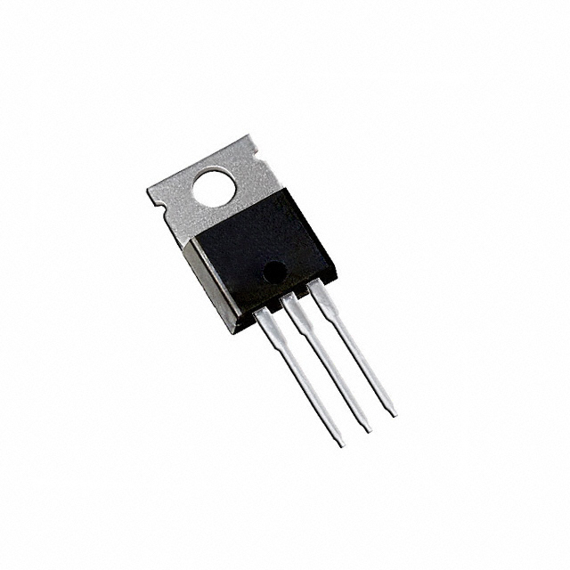
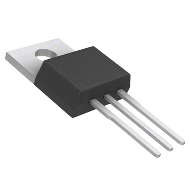
The STP360N4F6 is an N-Channel MOSFET manufactured by STMicroelectronics, rated for 40V drain-to-source voltage and 120A continuous drain current in a TO-220 through-hole package. This device is classified as obsolete, which necessitates identification of equivalent and substitute components for ongoing design support and procurement continuity. The part belongs to the DeepGATE™ and STripFET™ VI series and carries automotive-grade qualification under AEC-Q101.
Substiute Parts
Key Parameters
| Parameter | Value | Unit |
|---|---|---|
| Drain-to-Source Voltage (Vdss) | 40 | V |
| Continuous Drain Current (Id) @ 25°C | 120 | A |
| On-State Resistance (Rds On) @ 60A, 10V | 1.8 | mOhm |
| Gate Threshold Voltage (Vgs(th)) @ 250µA | 4.5 | V |
| Gate Charge (Qg) @ 10V | 340 | nC |
| Power Dissipation (Max) | 300 | W |
| Operating Temperature Range | -55 to 175 | °C |
| Package Type | TO-220-3 | — |
| Mounting Type | Through Hole | — |
Substitute Part Grouping Explanation
Substitution of the STP360N4F6 is determined by strict adherence to the following electrical and mechanical parameters:
Primary Substitution Criteria:
- Drain-to-Source Voltage (Vdss): Must equal 40V
- FET Type: Must be N-Channel
- Technology: Must be MOSFET (Metal Oxide)
- Package/Case: Must be TO-220-3 or compatible TO-220 variant
- Mounting Type: Must be Through Hole
- Operating Temperature Range: Must span -55°C to 175°C minimum
Secondary Compatibility Parameters:
- Continuous Drain Current (Id): Substitute must meet or exceed 120A @ 25°C
- On-State Resistance (Rds On): Lower or equivalent values indicate improved performance
- Gate Threshold Voltage (Vgs(th)): Must fall within ±20V gate voltage specification
- Power Dissipation: Substitute must support thermal requirements of the application
Substitute parts are grouped into two categories: Direct Equivalents (matching current rating and thermal characteristics) and Enhanced Substitutes (higher current ratings or improved electrical characteristics while maintaining voltage and package compatibility).
Parameter Comparison
| Part Number | Manufacturer | Vdss (V) | Id @ 25°C (A) | Rds On (mOhm) | Vgs(th) (V) | Qg (nC) | Power Dissipation (W) | Package | Status |
|---|---|---|---|---|---|---|---|---|---|
| STP360N4F6 | STMicroelectronics | 40 | 120 | 1.8 @ 60A | 4.5 | 340 | 300 | TO-220-3 | Obsolete |
| IPP015N04NGXKSA1 | Infineon Technologies | 40 | 120 | 1.5 @ 100A | 4.0 | 250 | 250 | TO-220-3 | Active |
| PSMN1R5-40PS,127 | Nexperia USA Inc. | 40 | 120 | 1.6 @ 25A | 4.0 | 136 | 338 | TO-220-3 | Obsolete |
| CSD18510KCS | Texas Instruments | 40 | 200 | 1.7 @ 100A | 2.3 | 75 | 250 | TO-220-3 | Active |
| AUIRFB8409 | Infineon Technologies | 40 | 195 | 1.3 @ 100A | 3.9 | 450 | 375 | TO-220-3 | Active |
| AUIRFB8407 | Infineon Technologies | 40 | 195 | 2.0 @ 100A | 4.0 | 225 | 230 | TO-220-3 | Active |
| IRFB7434PBF | Infineon Technologies | 40 | 195 | 1.6 @ 100A | 3.9 | 324 | 294 | TO-220-3 | Active |
| IRFB7430PBF | Infineon Technologies | 40 | 195 | 1.3 @ 100A | 3.9 | 460 | 375 | TO-220-3 | Active |
| IRFB3004PBF | Infineon Technologies | 40 | 195 | 1.75 @ 195A | 4.0 | 240 | 380 | TO-220-3 | Active |
| IRLB3034PBF | Infineon Technologies | 40 | 195 | 1.7 @ 195A | 2.5 | 162 | 375 | TO-220-3 | Not For New Designs |
Engineering Selection Recommendations
For Direct Replacement (Current Rating Match):
The IPP015N04NGXKSA1 from Infineon Technologies is the primary recommended substitute. This part maintains the 120A continuous drain current specification of the STP360N4F6 while offering improved electrical characteristics: lower on-state resistance (1.5 mOhm vs. 1.8 mOhm), reduced gate charge (250 nC vs. 340 nC), and active product status. The part carries ROHS3 compliance and operates across the identical temperature range (-55°C to 175°C). The TO-220-3 package ensures mechanical and thermal compatibility.
For Enhanced Performance (Higher Current Rating):
The AUIRFB8409, IRFB7430PBF, and IRFB7434PBF are suitable for applications requiring higher current capacity. These parts are rated for 195A continuous drain current, providing 62.5% higher current handling than the original STP360N4F6. All three maintain the 40V Vdss specification and TO-220-3 package format. The AUIRFB8409 offers the lowest on-state resistance (1.3 mOhm) and highest power dissipation rating (375W), making it suitable for high-efficiency applications. The IRFB7430PBF and IRFB7434PBF provide similar performance with slightly different gate charge and thermal characteristics.
For Specialized Applications:
The CSD18510KCS from Texas Instruments (NexFET™ series) provides 200A continuous drain current with exceptionally low gate charge (75 nC @ 4.5V) and reduced gate threshold voltage (2.3V), beneficial for applications requiring fast switching or lower gate drive power. This part is active and ROHS3 compliant.
Product Status Considerations:
All recommended active substitutes carry ROHS3 compliance and REACH unaffected status, matching the environmental and regulatory profile of the original STP360N4F6. The IRLB3034PBF, while electrically compatible, carries "Not For New Designs" status and should be avoided for new development projects.
Frequently Asked Questions (FAQ)
Q: Can the IPP015N04NGXKSA1 be used as a direct drop-in replacement for the STP360N4F6?
A: Yes. Both parts share identical voltage (40V), current (120A), and package (TO-220-3) specifications. The IPP015N04NGXKSA1 offers improved electrical performance with lower on-state resistance and gate charge. No circuit modifications are required.
Q: What is the difference between the AUIRFB8409 and IRFB7430PBF?
A: Both parts are rated for 195A at 40V in TO-220-3 packages and carry active status. The AUIRFB8409 has lower on-state resistance (1.3 mOhm vs. 1.3 mOhm) and higher power dissipation (375W vs. 375W). Gate charge differs: AUIRFB8409 at 450 nC versus IRFB7430PBF at 460 nC. Selection depends on specific application thermal and switching requirements.
Q: Why is the CSD18510KCS recommended despite its higher current rating?
A: The CSD18510KCS meets all substitution criteria: 40V Vdss, TO-220-3 package, through-hole mounting, and -55°C to 175°C operating range. Its 200A rating exceeds the 120A requirement, providing design margin. The exceptionally low gate charge (75 nC) reduces gate drive losses, beneficial for high-frequency switching applications.
Q: Are there package compatibility concerns when substituting TO-220AB variants?
A: TO-220AB and TO-220-3 are mechanically and thermally compatible. Both are three-lead through-hole packages with identical pin spacing and mounting footprints. Electrical performance is equivalent. Substitution between these variants is permissible.
Q: Should the IRLB3034PBF be considered for new designs?
A: No. The IRLB3034PBF carries "Not For New Designs" status, indicating manufacturer discontinuation of new production. While electrically compatible with the STP360N4F6, active alternatives such as IPP015N04NGXKSA1 or AUIRFB8409 are preferred for new development to ensure long-term supply availability.
Q: What is the significance of gate threshold voltage differences among substitutes?
A: Gate threshold voltage (Vgs(th)) determines the gate voltage required to initiate conduction. The STP360N4F6 specifies 4.5V @ 250µA. Substitutes range from 2.3V (CSD18510KCS) to 4.0V (IPP015N04NGXKSA1). Lower threshold voltages enable operation with reduced gate drive voltage, beneficial for low-voltage gate driver circuits. Higher threshold voltages provide greater noise immunity in noisy environments. Selection depends on gate driver capabilities and application requirements.
Q: How do gate charge differences affect circuit performance?
A: Gate charge (Qg) represents the total charge required to switch the MOSFET from off to on state. Lower gate charge reduces switching losses and gate driver power consumption. The STP360N4F6 requires 340 nC. The CSD18510KCS requires only 75 nC, reducing gate drive losses by 78%. Higher gate charge (e.g., IRFB7430PBF at 460 nC) increases switching losses but may provide improved EMI characteristics in some applications.
Q: What thermal considerations apply when selecting a substitute?
A: Power dissipation ratings vary among substitutes: STP360N4F6 at 300W, IPP015N04NGXKSA1 at 250W, and AUIRFB8409 at 375W. Higher power dissipation ratings indicate greater thermal capacity. On-state resistance (Rds On) directly affects power dissipation: lower resistance generates less heat at equivalent current levels. For thermally constrained applications, select substitutes with lower Rds On or higher power dissipation ratings.
Alternative Parts

SJ6012L2TP
Littelfuse Inc.
6 Alternative Parts

JMK107BBJ476MA-RE
Taiyo Yuden
10 Alternative Parts

GMK107BBJ475MA-T
Taiyo Yuden
5 Alternative Parts
SJ6020N2ARP
Littelfuse Inc.
3 Alternative Parts
SJ6025R2ATP
Littelfuse Inc.
4 Alternative Parts

2474-05L
API Delevan Inc.
1 Alternative Parts

4590R-684K
API Delevan Inc.
1 Alternative Parts

CM6560R-334
API Delevan Inc.
1 Alternative Parts

CM6460-104
API Delevan Inc.
1 Alternative Parts

5526-12
API Delevan Inc.
1 Alternative Parts