


Request Quote
(Ships tomorrow)
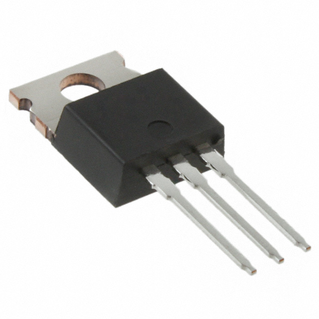
STP16NF25 N-Channel MOSFET Equivalent & Substitute Parts
Part Overview
The STP16NF25 is an N-Channel MOSFET manufactured by STMicroelectronics, rated for 250V drain-to-source voltage with 14A continuous drain current at 25°C. This device is packaged in a TO-220-3 through-hole configuration and is part of the STripFET™ II series. The STP16NF25 is classified as obsolete, making identification of equivalent and substitute parts necessary for ongoing design support and component procurement. Substitute parts must maintain electrical compatibility across voltage, current, and thermal specifications while accommodating the through-hole TO-220 mounting requirement.
Substiute Parts
Key Parameters
| Parameter | STP16NF25 Value | Unit |
|---|---|---|
| Drain-to-Source Voltage (Vdss) | 250 | V |
| Continuous Drain Current (Id) @ 25°C | 14 | A |
| Power Dissipation (Max) | 100 | W |
| Rds On (Max) @ 10V | 235 | mOhm |
| Gate Charge (Qg) @ 10V | 18 | nC |
| Operating Temperature Range | -55 to 150 | °C |
| Package Type | TO-220-3 | Through Hole |
| FET Type | N-Channel | — |
Substitute Part Grouping Explanation
Substitution eligibility for the STP16NF25 is determined by the following criteria:
Mandatory Compatibility Parameters:
- FET Type: N-Channel (all substitutes must be N-Channel)
- Package Type: TO-220-3 through-hole configuration
- Drain-to-Source Voltage (Vdss): Equal to or greater than 250V
- Continuous Drain Current (Id): Equal to or greater than 14A at 25°C
- Gate-Source Voltage (Vgs): ±20V maximum (all candidates meet this)
- Mounting Type: Through Hole
Electrical Performance Considerations:
- On-state resistance (Rds On) should not significantly exceed the reference value to maintain thermal performance
- Gate charge (Qg) affects switching characteristics and drive circuit requirements
- Power dissipation capability must support the application thermal budget
The substitute parts listed below meet the mandatory compatibility parameters. Variations in secondary parameters such as gate charge, input capacitance, and power dissipation reflect different semiconductor designs and manufacturing processes but do not preclude functional substitution when electrical specifications are satisfied.
Parameter Comparison
| Parameter | STP16NF25 | IRF630NPBF | IRF634PBF | IRF640NPBF | IRF644PBF | Unit |
|---|---|---|---|---|---|---|
| Manufacturer | STMicroelectronics | Infineon Technologies | Vishay Siliconix | Infineon Technologies | Vishay Siliconix | — |
| Vdss (Drain-to-Source Voltage) | 250 | 200 | 250 | 200 | 250 | V |
| Id @ 25°C (Continuous Drain Current) | 14 | 9.3 | 8.1 | 18 | 14 | A |
| Rds On (Max) @ 10V | 235 | 300 | 450 | 150 | 280 | mOhm |
| Power Dissipation (Max) | 100 | 82 | 74 | 150 | 125 | W |
| Gate Charge (Qg) @ 10V | 18 | 35 | 41 | 67 | 68 | nC |
| Operating Temperature Range | -55 to 150 | -55 to 175 | -55 to 150 | -55 to 175 | -55 to 150 | °C |
| Package | TO-220-3 | TO-220AB | TO-220AB | TO-220AB | TO-220AB | — |
| Product Status | Obsolete | Active | Active | Not For New Designs | Active | — |
| RoHS Status | ROHS3 Compliant | ROHS3 Compliant | ROHS3 Compliant | ROHS3 Compliant | ROHS3 Compliant | — |
Engineering Selection Recommendations
IRF644PBF (Vishay Siliconix)
The IRF644PBF provides the closest electrical match to the STP16NF25. Both devices are rated for 250V Vdss and 14A continuous drain current, with identical gate-source voltage specifications. The IRF644PBF is currently in active production status, ensuring long-term availability. RoHS3 compliance is confirmed. The IRF644PBF exhibits slightly higher on-state resistance (280 mOhm vs. 235 mOhm) and higher gate charge (68 nC vs. 18 nC), which may require minor drive circuit adjustments but does not preclude direct substitution. Power dissipation capability (125W) exceeds the STP16NF25 (100W), providing thermal margin. This part is the primary recommendation for direct replacement.
IRF640NPBF (Infineon Technologies)
The IRF640NPBF offers superior current handling (18A vs. 14A) and power dissipation (150W vs. 100W), making it suitable for applications requiring thermal headroom. However, the device is rated for 200V Vdss, which is below the STP16NF25 specification of 250V. This voltage limitation restricts its use to applications where the maximum operating voltage does not exceed 200V. The IRF640NPBF is classified as "Not For New Designs," indicating limited future availability. The significantly higher gate charge (67 nC vs. 18 nC) requires careful evaluation of drive circuit performance. This part is suitable only for voltage-constrained applications with established long-term inventory.
IRF630NPBF (Infineon Technologies)
The IRF630NPBF is rated for 200V Vdss and 9.3A continuous drain current, both below the STP16NF25 specifications. This device is not suitable as a direct substitute due to insufficient voltage and current ratings. The IRF630NPBF is classified as active, but its reduced electrical specifications limit its application scope. This part should be considered only for applications with reduced voltage and current requirements.
IRF634PBF (Vishay Siliconix)
The IRF634PBF matches the 250V Vdss rating but provides only 8.1A continuous drain current, below the STP16NF25 specification of 14A. The on-state resistance is significantly higher (450 mOhm vs. 235 mOhm), resulting in increased power dissipation and thermal stress. Power dissipation capability (74W) is also below the STP16NF25 (100W). This device is not recommended as a substitute for the STP16NF25 due to insufficient current and power handling capacity.
Frequently Asked Questions (FAQ)
Q: Can the IRF644PBF directly replace the STP16NF25 in existing designs?
A: Yes. The IRF644PBF meets all mandatory compatibility parameters: N-Channel FET type, TO-220-3 package, 250V Vdss rating, and 14A continuous drain current. Both devices share identical gate-source voltage specifications (±20V). The IRF644PBF is currently in active production, whereas the STP16NF25 is obsolete. Minor adjustments to gate drive circuitry may be necessary due to higher gate charge (68 nC vs. 18 nC), but electrical substitution is valid.
Q: Why is the IRF640NPBF not recommended despite higher current and power ratings?
A: The IRF640NPBF is rated for 200V Vdss, which is 50V below the STP16NF25 specification of 250V. Applications designed for 250V operation cannot use this device without risking component failure. Additionally, the IRF640NPBF is classified as "Not For New Designs," indicating limited future availability and potential supply discontinuation. The significantly higher gate charge also requires drive circuit re-evaluation.
Q: What is the impact of higher gate charge in substitute devices?
A: Gate charge (Qg) determines the amount of charge required to switch the FET on and off. The STP16NF25 has a gate charge of 18 nC, while the IRF644PBF has 68 nC. Higher gate charge requires longer switching times and higher drive current from the gate driver circuit. This may increase switching losses and heat generation. Drive circuit design must be verified to ensure adequate gate current and switching speed for the application.
Q: Are all substitute parts RoHS3 compliant?
A: Yes. All substitute parts listed (IRF630NPBF, IRF634PBF, IRF640NPBF, and IRF644PBF) are RoHS3 compliant, matching the STP16NF25 compliance status. All parts are also REACH unaffected and classified under ECCN EAR99.
Q: Can the IRF630NPBF or IRF634PBF be used in lower-voltage applications?
A: The IRF630NPBF and IRF634PBF have reduced electrical specifications compared to the STP16NF25. These devices are suitable only for applications with voltage and current requirements below their respective ratings. The IRF630NPBF (200V, 9.3A) and IRF634PBF (250V, 8.1A) should not be used in designs requiring the full 250V/14A capability of the STP16NF25.
Q: What is the difference between TO-220 and TO-220AB packaging?
A: TO-220 and TO-220AB are functionally equivalent three-lead through-hole packages with identical pin configurations and thermal characteristics. The designation "AB" indicates a specific variant within the TO-220 family. All substitute parts use TO-220AB packaging, which is mechanically and electrically compatible with TO-220-3 applications.
Q: Is inventory availability a factor in part selection?
A: Inventory levels are provided for reference but should not be the primary selection criterion. The IRF644PBF (3,281 pcs) has lower inventory than other substitutes, but active production status ensures continued availability. The IRF640NPBF (85,400 pcs) has high inventory but is classified as "Not For New Designs," indicating future supply uncertainty. Long-term design decisions should prioritize active production status over current inventory levels.
Alternative Parts

SJ6012L2TP
Littelfuse Inc.
6 Alternative Parts

JMK107BBJ476MA-RE
Taiyo Yuden
10 Alternative Parts

GMK107BBJ475MA-T
Taiyo Yuden
5 Alternative Parts
SJ6020N2ARP
Littelfuse Inc.
3 Alternative Parts
SJ6025R2ATP
Littelfuse Inc.
4 Alternative Parts

2474-05L
API Delevan Inc.
1 Alternative Parts

4590R-684K
API Delevan Inc.
1 Alternative Parts

CM6560R-334
API Delevan Inc.
1 Alternative Parts

CM6460-104
API Delevan Inc.
1 Alternative Parts

5526-12
API Delevan Inc.
1 Alternative Parts