


Request Quote
(Ships tomorrow)
STP13N65M2 Equivalent & Substitute Parts
Part Overview
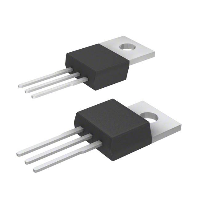
The STP13N65M2 is an N-Channel 650V 10A MOSFET manufactured by STMicroelectronics in the MDmesh™ M2 series. This through-hole TO-220 device is rated for 110W power dissipation and is designed for high-voltage switching applications. The part is Active status and RoHS3 compliant. Substitute parts are identified when equivalent electrical performance and mechanical compatibility are required due to inventory constraints, design optimization, or application-specific requirements.
Substiute Parts
Key Parameters
| Parameter | Value |
|---|---|
| Manufacturer Part Number | STP13N65M2 |
| Manufacturer | STMicroelectronics |
| FET Type | N-Channel |
| Drain to Source Voltage (Vdss) | 650 V |
| Continuous Drain Current (Id) @ 25°C | 10A (Tc) |
| Power Dissipation (Max) | 110W (Tc) |
| Rds On (Max) @ Id, Vgs | 430mOhm @ 5A, 10V |
| Gate Charge (Qg) (Max) @ Vgs | 17 nC @ 10 V |
| Vgs(th) (Max) @ Id | 4V @ 250µA |
| Vgs (Max) | ±25V |
| Input Capacitance (Ciss) (Max) @ Vds | 590 pF @ 100 V |
| Mounting Type | Through Hole |
| Package / Case | TO-220-3 |
| Operating Temperature | 150°C (TJ) |
| Product Status | Active |
| RoHS Status | ROHS3 Compliant |
Substitute Part Grouping Explanation
Substitute parts for the STP13N65M2 are qualified based on the following electrical and mechanical criteria:
Critical Parameters for Substitution:
- Drain to Source Voltage (Vdss): Must equal or exceed 650V
- Continuous Drain Current (Id): Must equal or exceed 10A at 25°C
- Power Dissipation: Must equal or exceed 110W
- Mounting Type: Through Hole
- Package: TO-220 or TO-220-3 compatible
- FET Type: N-Channel MOSFET
- Technology: Metal Oxide Semiconductor
Acceptable Variation Ranges:
- Vdss may exceed 650V (higher voltage rating acceptable)
- Id may exceed 10A (higher current rating acceptable)
- Power Dissipation may exceed 110W (higher rating acceptable)
- Rds On, Gate Charge, and Input Capacitance may vary within application tolerance
- Operating temperature range may differ
The following substitute parts meet these criteria and are qualified for direct replacement in applications where the STP13N65M2 is specified.
Parameter Comparison
| Parameter | STP13N65M2 (Main) | SPP11N80C3XKSA1 | IXTP8N70X2 | FCP600N60Z | IXTP8N70X2M |
|---|---|---|---|---|---|
| Manufacturer | STMicroelectronics | Infineon Technologies | IXYS | Fairchild Semiconductor | IXYS |
| FET Type | N-Channel | N-Channel | N-Channel | N-Channel | N-Channel |
| Vdss (V) | 650 | 800 | 700 | 600 | 700 |
| Id @ 25°C (A) | 10 | 11 | 8 | 7.4 | 4 |
| Power Dissipation (W) | 110 | 156 | 150 | 89 | 32 |
| Rds On (Max) @ Id, Vgs (mOhm) | 430 @ 5A, 10V | 450 @ 7.1A, 10V | 500 @ 500mA, 10V | 600 @ 3.7A, 10V | 550 @ 500mA, 10V |
| Gate Charge (nC) @ 10V | 17 | 85 | 12 | 26 | 12 |
| Vgs(th) (Max) @ Id (V) | 4 @ 250µA | 3.9 @ 680µA | 5 @ 250µA | 3.5 @ 250µA | 5 @ 250µA |
| Vgs (Max) (±V) | ±25 | ±20 | ±30 | ±20 | ±30 |
| Input Capacitance (pF) @ Vds | 590 @ 100V | 1600 @ 100V | 800 @ 10V | 1120 @ 25V | 800 @ 10V |
| Mounting Type | Through Hole | Through Hole | Through Hole | Through Hole | Through Hole |
| Package / Case | TO-220-3 | TO-220-3 | TO-220-3 | TO-220-3 | TO-220-3 Full Pack, Isolated Tab |
| Operating Temperature (°C) | 150 (TJ) | -55 ~ 150 (TJ) | -55 ~ 150 (TJ) | -55 ~ 150 (TJ) | -55 ~ 150 (TJ) |
| Product Status | Active | Active | Active | Active | Active |
| RoHS Status | ROHS3 Compliant | ROHS3 Compliant | ROHS3 Compliant | Not specified | ROHS3 Compliant |
Engineering Selection Recommendations
SPP11N80C3XKSA1 (Infineon Technologies CoolMOS™)
This substitute exceeds all critical parameters of the STP13N65M2. The 800V Vdss rating provides additional voltage margin, and the 11A continuous drain current exceeds the 10A requirement. Power dissipation of 156W exceeds the 110W specification. The part is Active status and RoHS3 compliant. Gate charge of 85 nC is higher than the main part, which may affect switching speed in gate-drive-limited applications. This part is suitable for applications requiring higher voltage or current headroom.
IXTP8N70X2 (IXYS Ultra X2)
This substitute meets the minimum current requirement at 8A, which is below the 10A specification of the main part. The 700V Vdss rating exceeds the 650V requirement. Power dissipation of 150W exceeds the 110W specification. The part is Active status and RoHS3 compliant. Gate charge of 12 nC is lower than the main part, enabling faster switching. This part is suitable for applications where current demand is below 10A or where lower gate charge is beneficial.
FCP600N60Z (Fairchild Semiconductor SuperFET® II)
This substitute has a Vdss rating of 600V, which is below the 650V specification of the main part. The continuous drain current of 7.4A is below the 10A requirement. Power dissipation of 89W is below the 110W specification. This part does not meet the minimum electrical requirements and is not recommended as a direct substitute for the STP13N65M2.
IXTP8N70X2M (IXYS Ultra X2 Isolated Tab)
This substitute has a continuous drain current of 4A, which is significantly below the 10A requirement of the main part. Power dissipation of 32W is substantially below the 110W specification. The isolated tab variant provides additional thermal isolation but does not meet the electrical performance requirements. This part is not suitable as a substitute for the STP13N65M2.
Frequently Asked Questions (FAQ)
Q: Can the SPP11N80C3XKSA1 be used as a direct replacement for the STP13N65M2?
A: The SPP11N80C3XKSA1 meets all critical electrical and mechanical requirements. It exceeds the voltage, current, and power dissipation specifications. Both parts are Active status and RoHS3 compliant. Direct substitution is electrically valid. However, the higher gate charge (85 nC vs. 17 nC) may require gate driver adjustment in applications with limited drive capability.
Q: Why does the IXTP8N70X2 have lower continuous drain current than the STP13N65M2?
A: The IXTP8N70X2 is rated for 8A continuous drain current at 25°C, compared to 10A for the STP13N65M2. This reflects different die design and thermal characteristics. The IXTP8N70X2 is suitable for applications requiring less than 10A; applications requiring the full 10A specification should use the STP13N65M2 or SPP11N80C3XKSA1.
Q: Are all substitute parts available in the same TO-220-3 package?
A: All substitute parts are available in TO-220-3 or compatible through-hole packages. The IXTP8N70X2M includes an isolated tab variant. Pin configuration and thermal characteristics may differ; verify PCB layout compatibility before substitution.
Q: What is the significance of gate charge differences between these parts?
A: Gate charge (Qg) determines the energy required to switch the MOSFET on and off. The STP13N65M2 has 17 nC gate charge, while the IXTP8N70X2 has 12 nC. Lower gate charge enables faster switching and reduces gate driver power dissipation. Higher gate charge (SPP11N80C3XKSA1 at 85 nC) requires more robust gate drive circuits.
Q: Can the FCP600N60Z be used in place of the STP13N65M2?
A: No. The FCP600N60Z does not meet the minimum electrical specifications. Its 600V Vdss rating is below the 650V requirement, continuous drain current of 7.4A is below the 10A requirement, and power dissipation of 89W is below the 110W specification. This part is not qualified as a substitute.
Q: What is the difference between the IXTP8N70X2 and IXTP8N70X2M?
A: Both parts are from the IXYS Ultra X2 series with 700V Vdss rating. The primary difference is the isolated tab variant in the IXTP8N70X2M, which provides electrical isolation between the tab and the source pin. The IXTP8N70X2M has a lower continuous drain current rating of 4A compared to 8A for the IXTP8N70X2, making it unsuitable for the STP13N65M2 application.
Q: Are all substitute parts RoHS3 compliant?
A: The SPP11N80C3XKSA1, IXTP8N70X2, and IXTP8N70X2M are RoHS3 compliant. The FCP600N60Z RoHS status is not specified in the provided data. Verify compliance requirements for your application before selection.
Q: What operating temperature range should be considered for substitution?
A: The STP13N65M2 is rated to 150°C junction temperature. All substitute parts (SPP11N80C3XKSA1, IXTP8N70X2, FCP600N60Z, IXTP8N70X2M) support -55°C to 150°C operating range, which exceeds the main part specification. Temperature performance is not a limiting factor for substitution.
Alternative Parts

SJ6012L2TP
Littelfuse Inc.
6 Alternative Parts

JMK107BBJ476MA-RE
Taiyo Yuden
10 Alternative Parts

GMK107BBJ475MA-T
Taiyo Yuden
5 Alternative Parts
SJ6020N2ARP
Littelfuse Inc.
3 Alternative Parts
SJ6025R2ATP
Littelfuse Inc.
4 Alternative Parts

2474-05L
API Delevan Inc.
1 Alternative Parts

4590R-684K
API Delevan Inc.
1 Alternative Parts

CM6560R-334
API Delevan Inc.
1 Alternative Parts

CM6460-104
API Delevan Inc.
1 Alternative Parts

5526-12
API Delevan Inc.
1 Alternative Parts