


Request Quote
(Ships tomorrow)
STP12PF06 Equivalent & Substitute Parts
Part Overview
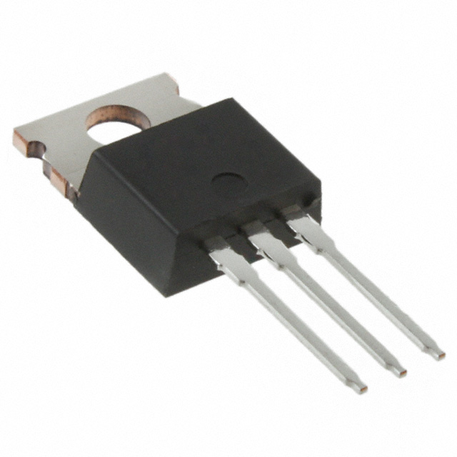
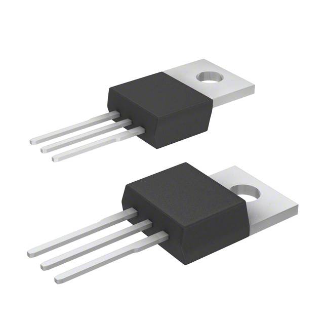
The STP12PF06 is a P-Channel MOSFET manufactured by STMicroelectronics, rated for 60V drain-to-source voltage with 12A continuous drain current at 25°C. This device is packaged in TO-220-3 and belongs to the STripFET™ II series. The part is classified as obsolete, making equivalent and substitute parts necessary for ongoing design support and procurement continuity.
Substiute Parts
Key Parameters
| Parameter | Value | Unit |
|---|---|---|
| FET Type | P-Channel | — |
| Drain to Source Voltage (Vdss) | 60 | V |
| Current - Continuous Drain (Id) @ 25°C | 12 | A (Tc) |
| Rds On (Max) @ Id, Vgs | 200 | mOhm @ 10A, 10V |
| Power Dissipation (Max) | 60 | W (Tc) |
| Operating Temperature Range | -55 to 175 | °C (TJ) |
| Package / Case | TO-220-3 | — |
| Mounting Type | Through Hole | — |
Substitute Part Grouping Explanation
Substitution of the STP12PF06 is determined by the following critical parameters:
Primary Substitution Criteria:
- FET Type: P-Channel (required match)
- Drain to Source Voltage (Vdss): Minimum 60V (equal or higher acceptable)
- Current - Continuous Drain (Id): Minimum 12A (equal or higher acceptable)
- Package / Case: TO-220-3 (mechanical compatibility required)
- Mounting Type: Through Hole (required match)
- Operating Temperature Range: -55°C to 175°C (required match)
Secondary Compatibility Factors:
- Rds On (Max): Lower values indicate improved performance
- Power Dissipation (Max): Higher values provide thermal margin
- Gate Charge (Qg): Lower values reduce switching losses
- Vgs(th) and Vgs (Max): Must remain within ±20V specification
All substitute parts listed meet or exceed the primary substitution criteria. Devices with higher current ratings, lower on-resistance, or greater power dissipation provide enhanced performance margins while maintaining full electrical and mechanical compatibility.
Parameter Comparison
| Parameter | STP12PF06 (Main) | FQP17P06 | IRF9Z24NPBF | IRF9Z24PBF | IRF9Z34PBF | SPP18P06PHXKSA1 |
|---|---|---|---|---|---|---|
| Manufacturer | STMicroelectronics | onsemi | Infineon Technologies | Vishay Siliconix | Vishay Siliconix | Infineon Technologies |
| FET Type | P-Channel | P-Channel | P-Channel | P-Channel | P-Channel | P-Channel |
| Vdss (V) | 60 | 60 | 55 | 60 | 60 | 60 |
| Id @ 25°C (A) | 12 | 17 | 12 | 11 | 18 | 18.7 |
| Rds On (Max) (mOhm) | 200 @ 10A, 10V | 120 @ 8.5A, 10V | 175 @ 7.2A, 10V | 280 @ 6.6A, 10V | 140 @ 11A, 10V | 130 @ 13.2A, 10V |
| Vgs(th) (Max) @ Id (V) | 4 @ 250µA | 4 @ 250µA | 4 @ 250µA | 4 @ 250µA | 4 @ 250µA | 4 @ 1mA |
| Gate Charge (Qg) (Max) @ 10V (nC) | 21 | 27 | 19 | 19 | 34 | 28 |
| Vgs (Max) (V) | ±20 | ±25 | ±20 | ±20 | ±20 | ±20 |
| Input Capacitance (Ciss) (Max) @ 25V (pF) | 850 | 900 | 350 | 570 | 1100 | 860 |
| Power Dissipation (Max) (W) | 60 | 79 | 45 | 60 | 88 | 81.1 |
| Operating Temperature (°C) | -55 to 175 | -55 to 175 | -55 to 175 | -55 to 175 | -55 to 175 | -55 to 175 |
| Package / Case | TO-220-3 | TO-220-3 | TO-220-3 | TO-220-3 | TO-220-3 | TO-220-3 |
| Mounting Type | Through Hole | Through Hole | Through Hole | Through Hole | Through Hole | Through Hole |
| Product Status | Obsolete | Active | Active | Active | Active | Active |
| RoHS Status | ROHS3 Compliant | ROHS3 Compliant | ROHS3 Compliant | ROHS3 Compliant | ROHS3 Compliant | ROHS3 Compliant |
Engineering Selection Recommendations
Primary Substitutes (Highest Compatibility):
IRF9Z24NPBF (Infineon Technologies) — This substitute matches the STP12PF06 in continuous drain current (12A) and maintains the 60V Vdss rating with a lower Vdss specification of 55V. The device is active and ROHS3 compliant. The lower on-resistance (175 mOhm) and reduced gate charge (19 nC) provide improved switching performance. This part is suitable for direct replacement in applications where the 55V rating is acceptable.
IRF9Z24PBF (Vishay Siliconix) — This substitute provides 60V Vdss and 11A continuous drain current, closely matching the STP12PF06 specifications. The device is active and ROHS3 compliant. The higher on-resistance (280 mOhm) represents a trade-off in thermal performance but maintains electrical compatibility. This part is suitable for applications with lower current demands or where thermal dissipation is not critical.
Performance-Enhanced Substitutes (Higher Current Ratings):
FQP17P06 (onsemi) — This substitute provides 60V Vdss with 17A continuous drain current, exceeding the STP12PF06 rating. The device is active and ROHS3 compliant. The significantly lower on-resistance (120 mOhm) and higher power dissipation (79W) provide enhanced thermal margin and reduced switching losses. This part is suitable for applications requiring improved performance headroom.
IRF9Z34PBF (Vishay Siliconix) — This substitute provides 60V Vdss with 18A continuous drain current, exceeding the STP12PF06 rating. The device is active and ROHS3 compliant. The lower on-resistance (140 mOhm) and higher power dissipation (88W) provide enhanced thermal performance. The higher gate charge (34 nC) requires consideration in high-frequency switching applications.
SPP18P06PHXKSA1 (Infineon Technologies) — This substitute provides 60V Vdss with 18.7A continuous drain current, exceeding the STP12PF06 rating. The device is active and ROHS3 compliant. The lower on-resistance (130 mOhm) and higher power dissipation (81.1W) provide enhanced thermal performance. This part is suitable for applications requiring maximum current capacity and thermal efficiency.
Frequently Asked Questions (FAQ)
Q: Can the STP12PF06 be replaced with any of these substitute parts?
A: All listed substitute parts meet the minimum electrical and mechanical requirements for substitution. The STP12PF06 is obsolete, making these active alternatives necessary for procurement. Selection depends on specific application requirements regarding current capacity, thermal dissipation, and switching characteristics.
Q: What is the key difference between the substitute parts?
A: The primary differences are continuous drain current ratings (11A to 18.7A), on-resistance values (120 to 280 mOhm), and power dissipation capabilities (45W to 88W). Higher current-rated devices provide improved thermal margins and lower on-resistance, reducing power losses. Selection should be based on application current requirements and thermal constraints.
Q: Are all substitute parts pin-compatible with the STP12PF06?
A: Yes. All substitute parts use the TO-220-3 package with identical pin configuration (Gate, Drain, Source). Through-hole mounting is consistent across all devices. Direct PCB replacement is possible without layout modifications.
Q: Does the lower Vdss rating of IRF9Z24NPBF (55V) affect compatibility?
A: The IRF9Z24NPBF has a 55V Vdss rating compared to the STP12PF06's 60V rating. This substitute is suitable only for applications where the maximum operating voltage does not exceed 55V. For applications requiring the full 60V rating, select FQP17P06, IRF9Z24PBF, IRF9Z34PBF, or SPP18P06PHXKSA1.
Q: Which substitute offers the best thermal performance?
A: The IRF9Z34PBF and SPP18P06PHXKSA1 provide the highest power dissipation ratings (88W and 81.1W respectively) and lowest on-resistance values (140 mOhm and 130 mOhm). These devices are optimal for applications with high current demands or stringent thermal requirements.
Q: Are there compliance differences between the substitute parts?
A: All substitute parts are ROHS3 compliant. IRF9Z24PBF and IRF9Z34PBF are REACH Affected, while IRF9Z24NPBF and SPP18P06PHXKSA1 are REACH Unaffected. Verify compliance requirements for your specific application and region.
Q: What is the impact of gate charge differences on circuit design?
A: Gate charge (Qg) affects switching speed and driver requirements. The STP12PF06 has 21 nC gate charge. Substitutes range from 19 nC (IRF9Z24NPBF, IRF9Z24PBF) to 34 nC (IRF9Z34PBF). Higher gate charge requires more driver current for equivalent switching speed. Verify gate driver capability before selecting high gate charge devices.
Q: Can these substitutes be used in high-frequency switching applications?
A: Yes, with consideration of gate charge and input capacitance. Lower gate charge devices (IRF9Z24NPBF at 19 nC) are preferable for high-frequency operation. Input capacitance ranges from 350 pF to 1100 pF; lower values reduce switching losses. Evaluate specific frequency requirements against device specifications.
Alternative Parts

SJ6012L2TP
Littelfuse Inc.
6 Alternative Parts

JMK107BBJ476MA-RE
Taiyo Yuden
10 Alternative Parts

GMK107BBJ475MA-T
Taiyo Yuden
5 Alternative Parts
SJ6020N2ARP
Littelfuse Inc.
3 Alternative Parts
SJ6025R2ATP
Littelfuse Inc.
4 Alternative Parts

2474-05L
API Delevan Inc.
1 Alternative Parts

4590R-684K
API Delevan Inc.
1 Alternative Parts

CM6560R-334
API Delevan Inc.
1 Alternative Parts

CM6460-104
API Delevan Inc.
1 Alternative Parts

5526-12
API Delevan Inc.
1 Alternative Parts