


Request Quote
(Ships tomorrow)
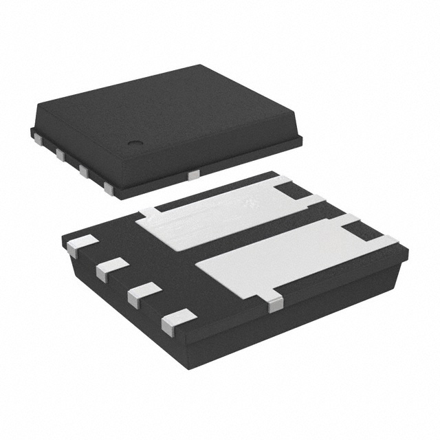
STL20DN10F7 Equivalent & Substitute Parts
Part Overview
The STL20DN10F7 is a dual N-channel MOSFET array manufactured by STMicroelectronics, rated for 100V drain-to-source voltage and 20A continuous drain current. This device is housed in a PowerFlat™ (5x6) surface mount package and is part of the DeepGATE™ and STripFET™ VII series. The product is currently obsolete, making identification of equivalent and substitute components necessary for ongoing design support, legacy system maintenance, and production continuity.
Substiute Parts
Key Parameters
| Parameter | Value | Unit |
|---|---|---|
| Drain to Source Voltage (Vdss) | 100 | V |
| Current - Continuous Drain (Id) @ 25°C | 20 | A |
| Rds On (Max) @ Id, Vgs | 67 @ 2.5A, 10V | mOhm |
| Vgs(th) (Max) @ Id | 4.5 @ 250µA | V |
| Gate Charge (Qg) (Max) @ Vgs | 7.8 @ 10V | nC |
| Input Capacitance (Ciss) (Max) @ Vds | 408 @ 50V | pF |
| Power - Max | 62.5 | W |
| Operating Temperature Range | -55 to 150 | °C (TJ) |
| Configuration | 2 N-Channel (Dual) | |
| Mounting Type | Surface Mount | |
| Package / Case | 8-PowerVDFN | |
| RoHS Status | ROHS3 Compliant | |
| Moisture Sensitivity Level (MSL) | 1 (Unlimited) |
Substitute Part Grouping Explanation
Substitution of the STL20DN10F7 is determined by the following critical electrical and mechanical parameters:
Electrical Compatibility Criteria:
- Drain to Source Voltage (Vdss): Must equal or exceed 100V
- Configuration: Must be dual N-channel (2 N-Channel)
- Operating Temperature Range: Must span -55°C to 150°C (TJ)
- Technology: Metal Oxide MOSFET
Mechanical Compatibility Criteria:
- Mounting Type: Surface Mount
- Pin count and footprint compatibility with application circuit design
Regulatory Compliance:
- RoHS3 Compliance required
- MSL rating of 1 (Unlimited) preferred for handling consistency
The SI7252DP-T1-GE3 from Vishay Siliconix meets these substitution criteria. While it features a different package type (PowerPAK® SO-8 Dual versus PowerFlat™ 5x6), it maintains electrical equivalence in voltage rating, dual N-channel configuration, and temperature range. The SI7252DP-T1-GE3 is an active product with superior current handling (36.7A versus 20A) and lower on-resistance characteristics, making it suitable for applications where the STL20DN10F7 is no longer available.
Parameter Comparison
| Parameter | STL20DN10F7 (Main) | SI7252DP-T1-GE3 (Substitute) | Unit |
|---|---|---|---|
| Manufacturer | STMicroelectronics | Vishay Siliconix | |
| Product Status | Obsolete | Active | |
| Drain to Source Voltage (Vdss) | 100 | 100 | V |
| Current - Continuous Drain (Id) @ 25°C | 20 | 36.7 | A |
| Rds On (Max) @ Id, Vgs | 67 @ 2.5A, 10V | 18 @ 15A, 10V | mOhm |
| Vgs(th) (Max) @ Id | 4.5 @ 250µA | 3.5 @ 250µA | V |
| Gate Charge (Qg) (Max) @ Vgs | 7.8 @ 10V | 27 @ 10V | nC |
| Input Capacitance (Ciss) (Max) @ Vds | 408 @ 50V | 1170 @ 50V | pF |
| Power - Max | 62.5 | 46 | W |
| Operating Temperature Range | -55 to 150 | -55 to 150 | °C (TJ) |
| Configuration | 2 N-Channel (Dual) | 2 N-Channel (Dual) | |
| Mounting Type | Surface Mount | Surface Mount | |
| Package / Case | 8-PowerVDFN | PowerPAK® SO-8 Dual | |
| RoHS Status | ROHS3 Compliant | ROHS3 Compliant | |
| Moisture Sensitivity Level (MSL) | 1 (Unlimited) | 1 (Unlimited) |
Engineering Selection Recommendations
Substitution Feasibility:
The SI7252DP-T1-GE3 is a valid electrical substitute for the STL20DN10F7 based on matching voltage rating (100V), dual N-channel configuration, and identical operating temperature range (-55°C to 150°C). Both devices maintain ROHS3 compliance and MSL rating of 1, ensuring regulatory and handling consistency.
Key Considerations:
-
Product Status: The SI7252DP-T1-GE3 is an active product with current manufacturing support and availability, whereas the STL20DN10F7 is obsolete. This transition provides long-term supply chain stability.
-
Package Transition: The substitute uses PowerPAK® SO-8 Dual packaging instead of PowerFlat™ (5x6). PCB layout and footprint modifications are required. Pin configuration must be verified against application schematics.
-
Electrical Performance: The SI7252DP-T1-GE3 offers superior current handling (36.7A versus 20A) and lower on-resistance (18mOhm versus 67mOhm at rated conditions). These characteristics provide improved thermal performance and reduced power dissipation in equivalent applications.
-
Gate Charge and Capacitance: The substitute exhibits higher gate charge (27nC versus 7.8nC) and input capacitance (1170pF versus 408pF). Gate drive circuit parameters may require adjustment to accommodate these differences.
-
Compliance Verification: Both devices carry ECCN EAR99 classification and identical HTSUS codes, confirming regulatory alignment for export and procurement purposes.
Frequently Asked Questions (FAQ)
Q: Can the SI7252DP-T1-GE3 directly replace the STL20DN10F7 without circuit modifications?
A: Electrical substitution is valid due to matching voltage rating and dual N-channel configuration. However, package geometry differs (PowerPAK® SO-8 Dual versus PowerFlat™ 5x6), requiring PCB footprint redesign. Gate drive circuit parameters may require adjustment due to higher gate charge characteristics.
Q: What is the primary reason for substituting the STL20DN10F7?
A: The STL20DN10F7 is classified as obsolete. The SI7252DP-T1-GE3 is an active product with ongoing manufacturing support, ensuring long-term availability and supply chain continuity.
Q: Are there compliance or regulatory differences between these devices?
A: Both devices are ROHS3 compliant, carry identical ECCN (EAR99) and HTSUS classifications, and maintain MSL rating of 1 (Unlimited). No regulatory barriers exist for substitution.
Q: How do the electrical performance characteristics compare?
A: The SI7252DP-T1-GE3 provides higher continuous drain current (36.7A versus 20A) and significantly lower on-resistance (18mOhm versus 67mOhm). Gate charge is higher (27nC versus 7.8nC), and input capacitance is increased (1170pF versus 408pF). These differences result in improved current handling and reduced conduction losses, with corresponding adjustments required in gate drive design.
Q: What package considerations apply to this substitution?
A: The STL20DN10F7 uses 8-PowerVDFN (PowerFlat™ 5x6) packaging, while the SI7252DP-T1-GE3 uses PowerPAK® SO-8 Dual packaging. Pin count remains at 8, but physical dimensions and land pattern differ. PCB layout redesign and component placement verification are mandatory before production implementation.
Q: Is the SI7252DP-T1-GE3 the only available substitute?
A: The SI7252DP-T1-GE3 is identified as the primary substitute based on provided electrical and mechanical parameters. Additional alternatives may exist within the Vishay Siliconix product portfolio, as indicated by the substitute cross-reference list (SP8K52FRATB, SH8KA7GZETB, SH8K37GZETB), but these are not detailed in the current engineering reference.
Alternative Parts

SJ6012L2TP
Littelfuse Inc.
6 Alternative Parts

JMK107BBJ476MA-RE
Taiyo Yuden
10 Alternative Parts

GMK107BBJ475MA-T
Taiyo Yuden
5 Alternative Parts
SJ6020N2ARP
Littelfuse Inc.
3 Alternative Parts
SJ6025R2ATP
Littelfuse Inc.
4 Alternative Parts

2474-05L
API Delevan Inc.
1 Alternative Parts

4590R-684K
API Delevan Inc.
1 Alternative Parts

CM6560R-334
API Delevan Inc.
1 Alternative Parts

CM6460-104
API Delevan Inc.
1 Alternative Parts

5526-12
API Delevan Inc.
1 Alternative Parts