


Request Quote
(Ships tomorrow)
STL15DN4F5 Equivalent & Substitute Parts
Part Overview
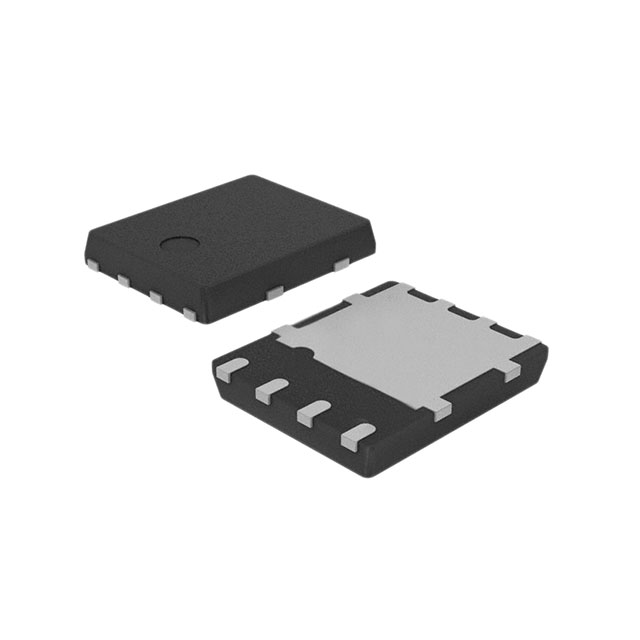
The STL15DN4F5 is a dual N-channel MOSFET manufactured by STMicroelectronics, configured as a 2N-channel device with a maximum drain-source voltage rating of 40V and continuous drain current of 60A. This component operates within the STripFET™ V series and is housed in a PowerFlat™ (5x6) surface mount package. The device maintains active product status and carries automotive-grade qualification under AEC-Q101 standards.
Substitute parts are identified when equivalent electrical performance parameters align with the main device specifications while accommodating different packaging configurations or manufacturer sourcing requirements. The substitute devices listed below are Infineon Technologies OptiMOS™ series MOSFETs that share critical electrical characteristics with the STL15DN4F5.
Substiute Parts
Key Parameters
| Parameter | Value | Unit |
|---|---|---|
| Drain-Source Voltage (Vdss) | 40 | V |
| Continuous Drain Current (Id) @ 25°C | 60 | A |
| On-State Resistance (Rds On) Max | 9 | mOhm @ 7.5A, 10V |
| Gate Threshold Voltage (Vgs(th)) Max | 4 | V @ 250µA |
| Gate Charge (Qg) Max | 25 | nC @ 10V |
| Input Capacitance (Ciss) Max | 1550 | pF @ 25V |
| Maximum Power Dissipation | 60 | W |
| Operating Temperature Range | -55 to 175 | °C (TJ) |
| Configuration | 2 N-Channel (Dual) | |
| FET Feature | Logic Level Gate | |
| Package Type | 8-PowerVDFN | |
| Mounting Type | Surface Mount | |
| Grade | Automotive | |
| Qualification | AEC-Q101 | |
| RoHS Status | ROHS3 Compliant | |
| Moisture Sensitivity Level (MSL) | 1 (Unlimited) |
Substitute Part Grouping Explanation
Substitution of the STL15DN4F5 with Infineon OptiMOS™ series devices is based on alignment of the following critical electrical parameters:
Voltage Rating Compatibility: All substitute parts maintain the same 40V drain-source voltage (Vdss) rating, ensuring compatibility with circuit voltage specifications.
Configuration Match: All substitute parts are configured as dual N-channel (2N-channel) MOSFETs with logic-level gate drive capability, matching the functional topology of the main device.
Operating Temperature Range: All substitute parts operate across the identical temperature range of -55°C to 175°C (TJ), maintaining thermal performance requirements.
Automotive Qualification: All substitute parts carry AEC-Q101 automotive qualification and are manufactured to automotive-grade standards, matching the qualification level of the STL15DN4F5.
Compliance Standards: All substitute parts are ROHS3 compliant with MSL rating of 1 (Unlimited), matching the environmental and handling requirements of the main device.
Current Rating Consideration: The substitute parts are rated for 20A continuous drain current, which is lower than the 60A rating of the STL15DN4F5. Substitution is valid only in applications where the actual operating current does not exceed 20A.
On-State Resistance: The substitute parts exhibit on-state resistance values (8.2 to 11.6 mOhm) that are comparable to the main device (9 mOhm), ensuring similar power dissipation characteristics within the reduced current rating.
Parameter Comparison
| Parameter | STL15DN4F5 (Main) | IPG20N04S4L08AATMA1 | IPG20N04S4L08ATMA1 | IPG20N04S4L11ATMA1 |
|---|---|---|---|---|
| Manufacturer | STMicroelectronics | Infineon Technologies | Infineon Technologies | Infineon Technologies |
| Series | STripFET™ V | OptiMOS™ | OptiMOS™ | OptiMOS™ |
| Vdss (V) | 40 | 40 | 40 | 40 |
| Id @ 25°C (A) | 60 | 20 | 20 | 20 |
| Rds On Max (mOhm) | 9 @ 7.5A, 10V | 8.2 @ 17A, 10V | 8.2 @ 17A, 10V | 11.6 @ 17A, 10V |
| Vgs(th) Max (V) | 4 @ 250µA | 2.2 @ 22µA | 2.2 @ 22µA | 2.2 @ 15µA |
| Qg Max (nC) | 25 @ 10V | 39 @ 10V | 39 @ 10V | 26 @ 10V |
| Ciss Max (pF) | 1550 @ 25V | 3050 @ 25V | 3050 @ 25V | 1990 @ 25V |
| Power Max (W) | 60 | 54 | 54 | 41 |
| Operating Temperature (°C) | -55 to 175 | -55 to 175 | -55 to 175 | -55 to 175 |
| Configuration | 2 N-Channel | 2 N-Channel | 2 N-Channel | 2 N-Channel |
| FET Feature | Logic Level Gate | Logic Level Gate | Logic Level Gate | Logic Level Gate |
| Package / Case | 8-PowerVDFN | 8-PowerVDFN | 8-PowerVDFN | 8-PowerVDFN |
| Mounting Type | Surface Mount | Surface Mount, Wettable Flank | Surface Mount | Surface Mount |
| Grade | Automotive | Automotive | Automotive | Automotive |
| Qualification | AEC-Q101 | AEC-Q101 | AEC-Q101 | AEC-Q101 |
| RoHS Status | ROHS3 Compliant | ROHS3 Compliant | ROHS3 Compliant | ROHS3 Compliant |
| MSL | 1 (Unlimited) | 1 (Unlimited) | 1 (Unlimited) | 1 (Unlimited) |
| Packaging | Cut Tape (CT) & Digi-Reel® | Tape & Reel (TR) | Tape & Reel (TR) | Cut Tape (CT) & Digi-Reel® |
Engineering Selection Recommendations
Primary Substitution Criteria: All three substitute parts meet the fundamental electrical and compliance requirements for substitution with the STL15DN4F5. Selection among the three Infineon devices depends on application-specific current requirements and packaging availability.
Current Rating Limitation: The substitute parts are rated for 20A continuous drain current. Applications operating the STL15DN4F5 at currents exceeding 20A cannot use these substitutes. Verify actual operating current in the target application before substitution.
Packaging Availability: The IPG20N04S4L11ATMA1 is available in Cut Tape (CT) & Digi-Reel® packaging, matching the packaging format of the STL15DN4F5. The IPG20N04S4L08AATMA1 and IPG20N04S4L08ATMA1 are supplied in Tape & Reel (TR) format, which may require different handling and procurement workflows.
On-State Resistance Performance: The IPG20N04S4L08AATMA1 and IPG20N04S4L08ATMA1 offer lower on-state resistance (8.2 mOhm) compared to the IPG20N04S4L11ATMA1 (11.6 mOhm), resulting in reduced power dissipation at equivalent current levels. The IPG20N04S4L11ATMA1 provides a middle-ground option with slightly higher resistance but lower gate charge and input capacitance.
Gate Charge Characteristics: The IPG20N04S4L11ATMA1 exhibits the lowest gate charge (26 nC), which may provide faster switching performance in gate-drive-limited applications. The IPG20N04S4L08AATMA1 and IPG20N04S4L08ATMA1 have higher gate charge (39 nC), which may require higher gate drive current.
Thermal Considerations: All substitute parts maintain the same operating temperature range (-55°C to 175°C). The lower maximum power rating of the IPG20N04S4L11ATMA1 (41W) compared to the main device (60W) reflects its lower current rating and should be considered in thermal design calculations.
Compliance and Qualification: All substitute parts carry identical automotive-grade qualification (AEC-Q101), ROHS3 compliance, and MSL rating (1 - Unlimited), ensuring compatibility with automotive supply chain requirements and environmental standards.
Frequently Asked Questions (FAQ)
Q: Can the STL15DN4F5 be directly replaced with any of the Infineon substitute parts?
A: Direct replacement is valid only in applications where the actual operating drain current does not exceed 20A. The substitute parts are rated for 20A continuous drain current, which is lower than the 60A rating of the STL15DN4F5. Verify the application's current requirements before substitution.
Q: What is the primary difference between the three Infineon substitute parts?
A: The three Infineon parts differ in on-state resistance, gate charge, input capacitance, and packaging format. The IPG20N04S4L08AATMA1 and IPG20N04S4L08ATMA1 offer lower on-state resistance (8.2 mOhm) but higher gate charge (39 nC). The IPG20N04S4L11ATMA1 has higher on-state resistance (11.6 mOhm) but lower gate charge (26 nC) and is available in Cut Tape & Digi-Reel® packaging matching the main device.
Q: Are all substitute parts automotive-qualified?
A: Yes. All three Infineon substitute parts carry AEC-Q101 automotive qualification and are manufactured to automotive-grade standards, matching the qualification level of the STL15DN4F5.
Q: What is the difference between the IPG20N04S4L08AATMA1 and IPG20N04S4L08ATMA1?
A: Both parts have identical electrical specifications (40V, 20A, 8.2 mOhm Rds On, 39 nC gate charge). The primary difference is the supplier device package designation: IPG20N04S4L08AATMA1 uses PG-TDSON-8-10 (Wettable Flank), while IPG20N04S4L08ATMA1 uses PG-TDSON-8-4. Both are supplied in Tape & Reel (TR) packaging.
Q: Can I use the IPG20N04S4L11ATMA1 as a direct replacement in terms of packaging?
A: The IPG20N04S4L11ATMA1 is available in Cut Tape (CT) & Digi-Reel® packaging, matching the packaging format of the STL15DN4F5. However, the other two Infineon substitutes are supplied in Tape & Reel (TR) format, which may require different procurement and handling procedures.
Q: How do the gate charge characteristics affect circuit performance?
A: Gate charge (Qg) determines the amount of charge required to switch the MOSFET on or off. The IPG20N04S4L11ATMA1 has lower gate charge (26 nC) compared to the IPG20N04S4L08AATMA1 and IPG20N04S4L08ATMA1 (39 nC each). Lower gate charge may enable faster switching in gate-drive-limited applications but requires less gate drive current.
Q: What does the input capacitance (Ciss) parameter indicate?
A: Input capacitance (Ciss) represents the total capacitance seen at the gate terminal and affects gate drive circuit design and switching speed. The STL15DN4F5 has 1550 pF, while the IPG20N04S4L11ATMA1 has 1990 pF and the other two Infineon parts have 3050 pF. Higher input capacitance requires higher gate drive current for equivalent switching speed.
Q: Are there any moisture sensitivity or handling differences?
A: All parts, including the main device and all substitutes, have MSL rating of 1 (Unlimited), indicating no moisture sensitivity limitations. Handling and storage requirements are equivalent across all devices.
Q: What compliance standards apply to all these parts?
A: All parts are ROHS3 compliant and REACH unaffected. All carry automotive-grade qualification under AEC-Q101 standards. All are classified under ECCN EAR99 and HTSUS 8541.29.0095 for export and tariff purposes.
Q: Can I substitute based on voltage rating alone?
A: No. While all parts share the same 40V voltage rating, substitution requires verification of current requirements, on-state resistance performance, gate drive characteristics, and thermal design compatibility. Current rating is the primary limiting factor for these substitutes.
Alternative Parts

SJ6012L2TP
Littelfuse Inc.
6 Alternative Parts

JMK107BBJ476MA-RE
Taiyo Yuden
10 Alternative Parts

GMK107BBJ475MA-T
Taiyo Yuden
5 Alternative Parts
SJ6020N2ARP
Littelfuse Inc.
3 Alternative Parts
SJ6025R2ATP
Littelfuse Inc.
4 Alternative Parts

2474-05L
API Delevan Inc.
1 Alternative Parts

4590R-684K
API Delevan Inc.
1 Alternative Parts

CM6560R-334
API Delevan Inc.
1 Alternative Parts

CM6460-104
API Delevan Inc.
1 Alternative Parts

5526-12
API Delevan Inc.
1 Alternative Parts