


Request Quote
(Ships tomorrow)
STI17NF25 Equivalent & Substitute Parts
Part Overview
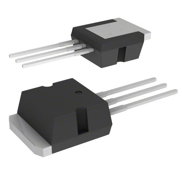
The STI17NF25 is an N-Channel MOSFET manufactured by STMicroelectronics, rated for 250V drain-to-source voltage with 17A continuous drain current at 25°C. This device is packaged in the I2PAK (TO-262-3 Long Leads) configuration and is designed for through-hole mounting applications. The part operates across a temperature range of -55°C to 150°C and dissipates up to 90W at the case temperature. The STI17NF25 is classified as obsolete, making identification of equivalent substitute components necessary for ongoing design support, maintenance, and production continuity.
Substiute Parts
Key Parameters
| Parameter | Value | Unit |
|---|---|---|
| Drain to Source Voltage (Vdss) | 250 | V |
| Continuous Drain Current (Id) @ 25°C | 17 | A |
| Rds On (Max) @ Id, Vgs | 165 | mOhm @ 8.5A, 10V |
| Gate Threshold Voltage (Vgs(th)) @ Id | 4 | V @ 250µA |
| Power Dissipation (Max) | 90 | W |
| Operating Temperature Range | -55 to 150 | °C |
| Package Type | I2PAK (TO-262-3) | Through Hole |
| FET Type | N-Channel | |
| Technology | MOSFET (Metal Oxide) |
Substitute Part Grouping Explanation
Substitution of the STI17NF25 is determined by the following critical electrical and mechanical parameters:
Voltage Rating Compatibility: The substitute part must support the application voltage requirements. The STI17NF25 is rated for 250V Vdss. Substitute parts with equal or higher voltage ratings are acceptable for direct replacement in circuits designed for this voltage class.
Current Handling Capability: The substitute must support the continuous drain current requirement of 17A at 25°C. Parts rated at or above this current level maintain functional equivalence in the application.
On-State Resistance (Rds On): The STI17NF25 exhibits 165mOhm maximum on-state resistance at 8.5A and 10V gate drive. Substitute parts with comparable or lower on-state resistance values ensure equivalent or improved thermal performance and power efficiency.
Gate Threshold Voltage: Both the main part and substitutes operate with a 4V gate threshold voltage at 250µA, ensuring compatible gate drive requirements.
Package and Mounting: The I2PAK (TO-262-3 Long Leads) through-hole package is the mechanical standard. Substitute parts must use identical or compatible package configurations to ensure PCB layout compatibility.
Temperature Operating Range: The STI17NF25 operates from -55°C to 150°C. Substitute parts with equal or extended temperature ranges maintain thermal compatibility.
Regulatory Compliance: Both the main part and substitutes must meet RoHS3 compliance and REACH unaffected status for equivalent regulatory standing.
Parameter Comparison
| Parameter | STI17NF25 | IRF640NLPBF | Unit |
|---|---|---|---|
| Manufacturer | STMicroelectronics | Infineon Technologies | |
| FET Type | N-Channel | N-Channel | |
| Technology | MOSFET (Metal Oxide) | MOSFET (Metal Oxide) | |
| Drain to Source Voltage (Vdss) | 250 | 200 | V |
| Continuous Drain Current (Id) @ 25°C | 17 | 18 | A |
| Rds On (Max) @ Id, Vgs | 165 @ 8.5A, 10V | 150 @ 11A, 10V | mOhm |
| Gate Threshold Voltage (Vgs(th)) @ Id | 4 @ 250µA | 4 @ 250µA | V |
| Gate Charge (Qg) (Max) @ Vgs | 29.5 @ 10V | 67 @ 10V | nC |
| Input Capacitance (Ciss) (Max) @ Vds | 1000 @ 25V | 1160 @ 25V | pF |
| Power Dissipation (Max) | 90 | 150 | W |
| Operating Temperature Range | -55 to 150 | -55 to 175 | °C |
| Package Type | I2PAK (TO-262-3) | TO-262 (TO-262-3) | |
| Mounting Type | Through Hole | Through Hole | |
| RoHS Status | ROHS3 Compliant | ROHS3 Compliant | |
| REACH Status | REACH Unaffected | REACH Unaffected | |
| Product Status | Obsolete | Obsolete |
Engineering Selection Recommendations
IRF640NLPBF as Primary Substitute:
The IRF640NLPBF manufactured by Infineon Technologies serves as a functional equivalent for the STI17NF25 in applications where the voltage rating differential is acceptable. The IRF640NLPBF is rated for 200V Vdss, which is 50V lower than the STI17NF25. This part is suitable for direct substitution in circuits operating at or below 200V. The IRF640NLPBF provides superior continuous drain current (18A versus 17A) and improved on-state resistance (150mOhm versus 165mOhm), resulting in lower power dissipation and improved thermal efficiency.
Both parts share identical gate threshold voltage specifications (4V @ 250µA), ensuring compatible gate drive circuits. The IRF640NLPBF operates across an extended temperature range (-55°C to 175°C) compared to the STI17NF25 (-55°C to 150°C), providing additional thermal margin in high-temperature applications.
Package compatibility is maintained, as both devices use TO-262-3 through-hole configurations. Both parts meet RoHS3 compliance and REACH unaffected status, ensuring equivalent regulatory standing for production and distribution.
Voltage Rating Consideration:
Applications requiring the full 250V rating of the STI17NF25 cannot use the IRF640NLPBF without circuit redesign. In such cases, alternative N-Channel MOSFETs rated for 250V or higher must be evaluated against the same substitution criteria.
Obsolescence Status:
Both the STI17NF25 and IRF640NLPBF are classified as obsolete. Long-term design strategies should consider transitioning to current-generation N-Channel MOSFET alternatives that meet the same electrical and mechanical requirements while offering active manufacturing support.
Frequently Asked Questions (FAQ)
Q: Can the IRF640NLPBF directly replace the STI17NF25 in all applications?
A: Direct replacement is possible only in applications operating at or below 200V. The IRF640NLPBF is rated for 200V Vdss, while the STI17NF25 is rated for 250V. Circuits designed for 250V operation require alternative substitutes with equivalent or higher voltage ratings.
Q: What are the key electrical differences between these parts?
A: The primary differences are voltage rating (250V versus 200V), gate charge (29.5nC versus 67nC), and power dissipation capability (90W versus 150W). The IRF640NLPBF offers lower on-state resistance (150mOhm versus 165mOhm) and higher continuous drain current (18A versus 17A), resulting in improved efficiency and thermal performance.
Q: Are the packages physically compatible?
A: Yes. Both the STI17NF25 and IRF640NLPBF use TO-262-3 Long Leads through-hole packages. PCB layouts designed for the STI17NF25 accommodate the IRF640NLPBF without modification.
Q: Do these parts have the same gate drive requirements?
A: Yes. Both parts share identical gate threshold voltage specifications (4V @ 250µA) and maximum gate voltage ratings (±20V). Existing gate drive circuits require no modification for substitution.
Q: What is the impact of the higher gate charge in the IRF640NLPBF?
A: The IRF640NLPBF exhibits higher gate charge (67nC versus 29.5nC at 10V). This results in longer switching times and increased gate drive power requirements. High-frequency switching applications may experience reduced efficiency with the IRF640NLPBF compared to the STI17NF25.
Q: Are both parts RoHS and REACH compliant?
A: Yes. Both the STI17NF25 and IRF640NLPBF are RoHS3 compliant and REACH unaffected, meeting current regulatory requirements for electronic component manufacturing and distribution.
Q: Why are both parts classified as obsolete?
A: Obsolescence indicates that these parts are no longer in active production. Manufacturers have transitioned to newer MOSFET technologies offering improved performance, efficiency, and integration. Long-term production strategies should incorporate current-generation alternatives.
Q: What should be considered when selecting a substitute for new designs?
A: New designs should prioritize current-generation N-Channel MOSFETs with active manufacturing support. Selection criteria include voltage rating, current capacity, on-state resistance, thermal performance, package compatibility, and compliance certifications. Obsolete parts should be used only for legacy system maintenance and repair.
Alternative Parts

SJ6012L2TP
Littelfuse Inc.
6 Alternative Parts

JMK107BBJ476MA-RE
Taiyo Yuden
10 Alternative Parts

GMK107BBJ475MA-T
Taiyo Yuden
5 Alternative Parts
SJ6020N2ARP
Littelfuse Inc.
3 Alternative Parts
SJ6025R2ATP
Littelfuse Inc.
4 Alternative Parts

2474-05L
API Delevan Inc.
1 Alternative Parts

4590R-684K
API Delevan Inc.
1 Alternative Parts

CM6560R-334
API Delevan Inc.
1 Alternative Parts

CM6460-104
API Delevan Inc.
1 Alternative Parts

5526-12
API Delevan Inc.
1 Alternative Parts