


Request Quote
(Ships tomorrow)
STGW80V60DF IGBT Equivalent & Substitute Parts
Part Overview
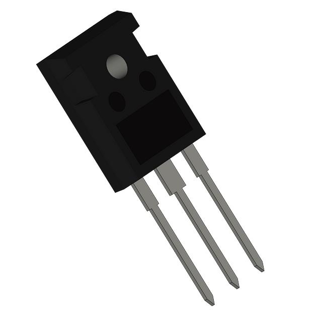
The STGW80V60DF is a Trench Field Stop IGBT manufactured by STMicroelectronics, rated for 600 V collector-emitter breakdown voltage and 120 A maximum collector current. This device is packaged in TO-247-3 with exposed pad configuration for through-hole mounting applications. The part is designated as Last Time Buy, indicating production discontinuation. Identification of equivalent and substitute parts is necessary to ensure design continuity and procurement availability for applications requiring 600 V IGBT functionality in the 100–120 A current range.
Substiute Parts
Key Parameters
| Parameter | Value | Unit |
|---|---|---|
| Voltage - Collector Emitter Breakdown (Max) | 600 | V |
| Current - Collector (Ic) (Max) | 120 | A |
| Current - Collector Pulsed (Icm) | 240 | A |
| Power - Max | 469 | W |
| Vce(on) (Max) @ Vge, Ic | 2.3 V @ 15 V, 80 A | V |
| Gate Charge | 448 | nC |
| Switching Energy (on/off) | 1.8 / 1.0 | mJ / mJ |
| Td (on/off) @ 25°C | 60 / 220 | ns / ns |
| Reverse Recovery Time (trr) | 60 | ns |
| Operating Temperature Range | -55 to 175 | °C (TJ) |
| Package / Case | TO-247-3 Exposed Pad | — |
| Mounting Type | Through Hole | — |
| IGBT Type | Trench Field Stop | — |
| RoHS Status | ROHS3 Compliant | — |
Substitute Part Grouping Explanation
Substitution of the STGW80V60DF is determined by alignment of the following critical parameters:
Voltage Rating: All substitute parts must maintain 600 V collector-emitter breakdown voltage to ensure safe operation within the same circuit topology. The STGWA75H65DFB2 operates at 650 V, which is acceptable for 600 V applications due to voltage derating margin.
Current Rating: The main part is rated for 120 A maximum collector current. Substitute parts with 100–120 A ratings are functionally equivalent. Parts rated below 100 A (such as IXGH36N60B3 at 92 A) operate within reduced current capacity and are classified as similar alternatives rather than direct equivalents.
Package and Mounting: All substitute parts use TO-247-3 through-hole mounting, ensuring mechanical and thermal interface compatibility.
IGBT Type: Trench Field Stop and Field Stop variants are interchangeable based on switching energy and gate charge characteristics. PT (Punch-Through) type IGBTs from IXYS represent alternative semiconductor architectures with different switching profiles.
Compliance: All parts listed are ROHS3 compliant and REACH unaffected, meeting regulatory requirements for the STGW80V60DF application.
Parameter Comparison
| Part Number | Manufacturer | Vce(sat) Max (V) | Ic Max (A) | Icm (A) | Power Max (W) | Gate Charge (nC) | Switching Energy On/Off (mJ) | Td on/off (ns) | Tj Range (°C) | Product Status |
|---|---|---|---|---|---|---|---|---|---|---|
| STGW80V60DF | STMicroelectronics | 2.3 | 120 | 240 | 469 | 448 | 1.8 / 1.0 | 60 / 220 | -55 to 175 | Last Time Buy |
| STGWA75H65DFB2 | STMicroelectronics | 2.0 | 115 | 225 | 357 | 207 | 1.428 / 1.05 | 28 / 100 | -55 to 175 | Active |
| FGH60N60SMD | onsemi | 2.5 | 120 | 180 | 600 | 189 | 1.26 / 0.45 | 18 / 104 | -55 to 175 | Active |
| FGH60N60SFDTU | onsemi | 2.9 | 120 | 180 | 378 | 198 | 1.79 / 0.67 | 22 / 134 | -55 to 150 | Active |
| IGW50N60H3FKSA1 | Infineon Technologies | 2.3 | 100 | 200 | 333 | 315 | 2.36 / — | 23 / 235 | -40 to 175 | Active |
| IGW50N60TFKSA1 | Infineon Technologies | 2.0 | 100 | 150 | 333 | 310 | 2.6 / — | 26 / 299 | -40 to 175 | Active |
| IKW50N60H3FKSA1 | Infineon Technologies | 2.3 | 100 | 200 | 333 | 315 | 2.36 / — | 23 / 235 | -40 to 175 | Active |
| IXXH50N60B3 | IXYS | 1.8 | 120 | 200 | 600 | 70 | 0.67 / 0.74 | 27 / 100 | Not Specified | Active |
| IXXH50N60B3D1 | IXYS | 1.8 | 120 | 200 | 600 | 70 | 0.67 / 0.74 | 27 / 100 | Not Specified | Active |
| IXGH36N60B3 | IXYS | 1.8 | 92 | 200 | 250 | 80 | 0.54 / 0.80 | 19 / 125 | -55 to 150 | Active |
| AOK50B60D1 | Alpha & Omega Semiconductor Inc. | 2.4 | 100 | 168 | 312 | 64 | 2.37 / 0.50 | 26 / 68 | -55 to 150 | Not For New Designs |
Engineering Selection Recommendations
Direct Equivalent (Manufacturer Recommended):
STGWA75H65DFB2 is the manufacturer-recommended substitute. This STMicroelectronics part maintains the same Trench Field Stop architecture and operating temperature range (-55°C to 175°C). The 650 V rating provides voltage margin above the 600 V specification. Collector current is rated at 115 A, which is within 4% of the original 120 A specification. This part is in Active product status, ensuring long-term availability and supply continuity.
Primary Alternatives (Active Status, Full Voltage/Current Compatibility):
FGH60N60SMD and IXXH50N60B3 / IXXH50N60B3D1 are functionally equivalent at 120 A / 600 V ratings. FGH60N60SMD is a Field Stop architecture from onsemi with superior power dissipation (600 W) and lower switching energy. IXXH50N60B3 variants employ PT (Punch-Through) architecture with reduced gate charge (70 nC) and lower Vce(sat) (1.8 V), resulting in improved efficiency. Both are ROHS3 compliant and in Active production status.
Secondary Alternatives (100 A Current Rating):
IGW50N60H3FKSA1, IGW50N60TFKSA1, and IKW50N60H3FKSA1 are Infineon TrenchStop® devices rated for 100 A maximum collector current. These parts are suitable for applications where current demand does not exceed 100 A. All three maintain 600 V voltage rating and -40°C to 175°C operating range. These parts are in Active status and ROHS3 compliant.
Limited Substitution (Reduced Current Rating):
IXGH36N60B3 is rated for 92 A maximum collector current and 250 W power dissipation. This part is suitable only for applications with current requirements below 92 A. It is in Active status and ROHS3 compliant but represents a downgrade in current capacity.
Not Recommended for New Designs:
AOK50B60D1 is designated Not For New Designs and should not be selected for new applications despite meeting voltage and current specifications.
Frequently Asked Questions (FAQ)
Q: Can STGWA75H65DFB2 directly replace STGW80V60DF in existing designs?
A: Yes. STGWA75H65DFB2 is the manufacturer-recommended substitute. The 650 V rating is compatible with 600 V applications. Collector current (115 A) is within acceptable tolerance of the original 120 A specification. Both parts use TO-247-3 through-hole packaging and share identical operating temperature range (-55°C to 175°C). No circuit modifications are required.
Q: What is the difference between Trench Field Stop and Field Stop IGBT architectures?
A: Both architectures are field-stop variants that reduce reverse recovery time and switching losses compared to conventional IGBTs. Trench Field Stop (STGW80V60DF, STGWA75H65DFB2) uses trench gate geometry. Field Stop (FGH60N60SMD, FGH60N60SFDTU) uses planar gate geometry. Switching energy and gate charge characteristics differ between architectures, but both are suitable for the same voltage and current classes.
Q: Are PT (Punch-Through) type IGBTs from IXYS compatible with the STGW80V60DF?
A: Yes, IXXH50N60B3 and IXXH50N60B3D1 are functionally compatible at 120 A / 600 V ratings. PT architecture offers lower gate charge (70 nC versus 448 nC) and lower Vce(sat) (1.8 V versus 2.3 V), resulting in reduced switching losses and improved efficiency. Circuit performance may improve with PT devices, but gate drive timing may require adjustment due to lower gate charge.
Q: Can I use a 100 A rated IGBT in place of the 120 A STGW80V60DF?
A: Yes, if the application current demand does not exceed 100 A. IGW50N60H3FKSA1, IGW50N60TFKSA1, and IKW50N60H3FKSA1 are rated for 100 A and are suitable for applications with maximum current below 100 A. These parts maintain 600 V voltage rating and are in Active production status. Verify that the application does not require the full 120 A capacity before substitution.
Q: What is the significance of the TO-247-3 package with exposed pad?
A: The exposed pad provides direct thermal contact to the mounting surface, improving heat dissipation. All substitute parts listed use TO-247-3 packaging, ensuring mechanical and thermal interface compatibility. The exposed pad design is standard across all listed alternatives.
Q: Are all listed substitute parts ROHS3 compliant?
A: Yes. All substitute parts listed are ROHS3 compliant and REACH unaffected, meeting regulatory requirements equivalent to the STGW80V60DF. Compliance status is consistent across all alternatives.
Q: Why is AOK50B60D1 listed if it is Not For New Designs?
A: AOK50B60D1 is included for reference in applications using legacy designs. This part should not be selected for new product development. Active alternatives such as FGH60N60SMD, IXXH50N60B3, or STGWA75H65DFB2 are recommended for all new designs.
Q: What is the impact of different gate charge values on circuit design?
A: Gate charge affects gate drive circuit design and switching speed. STGW80V60DF has 448 nC gate charge, while IXXH50N60B3 has 70 nC. Lower gate charge reduces gate drive power dissipation and allows faster switching. Higher gate charge requires more robust gate drive circuitry but may provide better noise immunity. Gate drive circuit adjustment may be necessary when substituting parts with significantly different gate charge values.
Q: Can I substitute a part with higher voltage rating (e.g., 650 V) in a 600 V application?
A: Yes. STGWA75H65DFB2 is rated for 650 V and is suitable for 600 V applications. Higher voltage rating provides design margin and does not negatively impact performance. However, parts with lower voltage ratings (below 600 V) are not acceptable for 600 V applications.
Alternative Parts

SJ6012L2TP
Littelfuse Inc.
6 Alternative Parts

JMK107BBJ476MA-RE
Taiyo Yuden
10 Alternative Parts

GMK107BBJ475MA-T
Taiyo Yuden
5 Alternative Parts
SJ6020N2ARP
Littelfuse Inc.
3 Alternative Parts
SJ6025R2ATP
Littelfuse Inc.
4 Alternative Parts

2474-05L
API Delevan Inc.
1 Alternative Parts

4590R-684K
API Delevan Inc.
1 Alternative Parts

CM6560R-334
API Delevan Inc.
1 Alternative Parts

CM6460-104
API Delevan Inc.
1 Alternative Parts

5526-12
API Delevan Inc.
1 Alternative Parts