


Request Quote
(Ships tomorrow)
STGW40H65DFB IGBT Equivalent & Substitute Parts
Part Overview
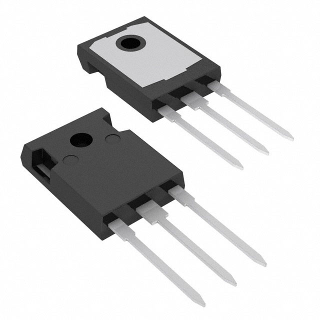
The STGW40H65DFB is an IGBT (Insulated Gate Bipolar Transistor) manufactured by STMicroelectronics, classified as a Trench Field Stop device rated for 650V collector-emitter breakdown voltage and 80A continuous collector current. The device is packaged in TO-247-3 through-hole configuration with a maximum power dissipation of 283W. Product status is Active with full RoHS3 compliance and unlimited moisture sensitivity level (MSL 1).
Equivalent and substitute parts are identified based on matching or exceeding the electrical performance parameters within the 650V voltage class and similar current ratings, while maintaining compatible through-hole packaging and thermal characteristics suitable for direct circuit board replacement or functional equivalence in power conversion applications.
Substiute Parts
Key Parameters
| Parameter | Value | Unit |
|---|---|---|
| Voltage - Collector Emitter Breakdown (Max) | 650 | V |
| Current - Collector (Ic) (Max) | 80 | A |
| Current - Collector Pulsed (Icm) | 160 | A |
| Vce(on) (Max) @ Vge, Ic | 2V @ 15V, 40A | V |
| Power - Max | 283 | W |
| Gate Charge | 210 | nC |
| Switching Energy (on/off) | 498µJ / 363µJ | µJ |
| Td (on/off) @ 25°C | 40ns / 142ns | ns |
| Operating Temperature Range | -55°C to 175°C | °C (TJ) |
| Package / Case | TO-247-3 | — |
| Mounting Type | Through Hole | — |
| RoHS Status | ROHS3 Compliant | — |
Substitute Part Grouping Explanation
Substitute parts are classified into two categories based on parametric alignment with the STGW40H65DFB:
Parametric Equivalents share identical or near-identical electrical specifications across all critical parameters: 650V breakdown voltage, 80A continuous collector current, 283W power rating, TO-247-3 packaging, and through-hole mounting. These parts are direct functional replacements with no circuit redesign required.
Similar Parts maintain the 650V voltage class and TO-247-3 package but differ in one or more of the following parameters: continuous collector current (ranging from 74A to 85A), maximum power dissipation (227W to 536W), gate charge (68nC to 436nC), switching energy characteristics, or thermal performance. Similar parts are suitable for applications where the specific current or power rating difference does not compromise circuit operation.
Key substitution criteria:
- Voltage - Collector Emitter Breakdown: 650V (mandatory)
- Package / Case: TO-247-3 (mandatory for direct board replacement)
- Mounting Type: Through Hole (mandatory)
- Current - Collector (Ic): 74A minimum to 85A maximum (acceptable range)
- Operating Temperature: -40°C to -55°C minimum; 175°C maximum
- RoHS3 Compliance: Required
- Input Type: Standard (mandatory)
Parameter Comparison
| Part Number | Manufacturer | Voltage (V) | Ic (A) | Icm (A) | Vce(on) (V) | Power (W) | Gate Charge (nC) | Td on/off (ns) | Package | Temp Range (°C) |
|---|---|---|---|---|---|---|---|---|---|---|
| STGW40H65DFB | STMicroelectronics | 650 | 80 | 160 | 2.0 @ 15V, 40A | 283 | 210 | 40 / 142 | TO-247-3 | -55 to 175 |
| STGW40H65FB | STMicroelectronics | 650 | 80 | 160 | 2.3 @ 15V, 40A | 283 | 210 | 40 / 142 | TO-247-3 | -55 to 175 |
| STGWA40H65FB | STMicroelectronics | 650 | 80 | 160 | 2.0 @ 15V, 40A | 283 | 210 | 40 / 142 | TO-247-3 | -55 to 175 |
| FGH40T65SHDF-F155 | onsemi | 650 | 80 | 120 | 1.81 @ 15V, 40A | 268 | 68 | 18 / 64 | TO-247-3 | -55 to 175 |
| IGW30N65L5XKSA1 | Infineon Technologies | 650 | 85 | 120 | 1.35 @ 15V, 30A | 227 | 168 | 33 / 308 | TO-247-3 | -40 to 175 |
| IGW40N65F5FKSA1 | Infineon Technologies | 650 | 74 | 120 | 2.1 @ 15V, 40A | 255 | 95 | 19 / 160 | TO-247-3 | -40 to 175 |
| IGW40N65H5FKSA1 | Infineon Technologies | 650 | 74 | 120 | 2.1 @ 15V, 40A | 255 | 95 | 22 / 165 | TO-247-3 | -40 to 175 |
| IGW50N65F5FKSA1 | Infineon Technologies | 650 | 80 | 150 | 2.1 @ 15V, 50A | 305 | 120 | 21 / 175 | TO-247-3 | -40 to 175 |
| IKW30N65EL5XKSA1 | Infineon Technologies | 650 | 85 | 120 | 1.35 @ 15V, 30A | 227 | 168 | 33 / 308 | TO-247-3 | -40 to 175 |
| IKW75N65EL5XKSA1 | Infineon Technologies | 650 | 80 | 300 | 1.35 @ 15V, 75A | 536 | 436 | 40 / 275 | TO-247-3 | -40 to 175 |
| NGTB40N65FL2WG | onsemi | 650 | 80 | 160 | 2.0 @ 15V, 40A | 366 | 170 | 84 / 177 | TO-247-3 | -55 to 175 |
Engineering Selection Recommendations
Parametric Equivalent Selection:
STGW40H65FB and STGWA40H65FB are parametric equivalents of the STGW40H65DFB. Both devices are manufactured by STMicroelectronics, maintain identical voltage and current ratings, and share the same TO-247-3 package. STGW40H65FB differs only in Vce(on) specification (2.3V versus 2.0V at test conditions), representing a minor on-state voltage variation within acceptable design margins. STGWA40H65FB features extended lead length in the TO-247 package configuration but maintains electrical equivalence. Both parts carry Active product status and full RoHS3 compliance. Selection between these equivalents depends on lead length requirements and on-state voltage tolerance in the target application.
Similar Part Selection for Current and Power Margin Applications:
FGH40T65SHDF-F155 (onsemi) maintains 80A continuous current and 650V voltage rating with improved switching characteristics (lower gate charge of 68nC and faster switching times: 18ns/64ns). This device is suitable for applications requiring reduced switching losses. Power rating of 268W is slightly lower than the main part, requiring thermal design verification.
IGW50N65F5FKSA1 (Infineon Technologies) provides 80A continuous current with enhanced power dissipation capability (305W), making it suitable for high-power applications. Gate charge of 120nC and switching times of 21ns/175ns represent moderate switching performance. Operating temperature minimum of -40°C (versus -55°C for the main part) should be verified against application requirements.
IKW75N65EL5XKSA1 (Infineon Technologies) is rated for 80A continuous current with significantly higher power dissipation (536W) and pulsed current capability (300A). This device is suitable for applications requiring substantial thermal headroom or high peak current transients. Gate charge of 436nC and switching times of 40ns/275ns indicate higher switching energy; circuit design must accommodate these characteristics.
Lower Current Alternatives:
IGW30N65L5XKSA1 and IKW30N65EL5XKSA1 (Infineon Technologies) are rated for 85A continuous current with reduced power dissipation (227W). These devices are suitable for applications where the 80A rating of the main part exceeds system requirements. Operating temperature minimum of -40°C applies to both devices.
IGW40N65F5FKSA1 and IGW40N65H5FKSA1 (Infineon Technologies) are rated for 74A continuous current with 255W power dissipation. These devices are suitable for applications with current requirements below 80A. Switching energy characteristics differ between the two variants (360µJ/100µJ versus 390µJ/120µJ for on/off), allowing selection based on specific switching loss requirements.
onsemi Alternative:
NGTB40N65FL2WG (onsemi) matches the 80A continuous current and 650V voltage rating with identical Vce(on) specification (2.0V @ 15V, 40A). Power dissipation is higher at 366W. Gate charge of 170nC and switching times of 84ns/177ns indicate higher switching losses compared to the main part. Operating temperature range matches the main part (-55°C to 175°C). This device is suitable for applications where onsemi device qualification is required.
Compliance and Certification:
All substitute parts listed carry RoHS3 compliance and REACH Unaffected status, matching the regulatory profile of the main part. All devices are classified as Active products with current manufacturing support. Moisture sensitivity level (MSL 1 - Unlimited) is consistent across STMicroelectronics and Infineon devices. onsemi devices do not specify MSL classification.
Frequently Asked Questions (FAQ)
Q: Can STGW40H65FB be used as a direct replacement for STGW40H65DFB?
A: Yes. STGW40H65FB is a parametric equivalent with identical voltage, current, power, and package specifications. The only difference is Vce(on) specification (2.3V versus 2.0V at 15V, 40A test conditions). This represents a 0.3V increase in on-state voltage, which may increase power dissipation by approximately 1.2W at 40A continuous current. Thermal design verification is recommended if the application operates at maximum current continuously.
Q: What is the difference between STGWA40H65FB and STGW40H65FB?
A: STGWA40H65FB features extended lead length in the TO-247 package (designated as TO-247 Long Leads) compared to standard TO-247-3 leads on STGW40H65FB. Electrical specifications are identical. Selection depends on PCB layout requirements and lead length compatibility with existing board designs.
Q: Can lower-current devices like IGW30N65L5XKSA1 (85A) replace the 80A STGW40H65DFB?
A: Yes, for applications where continuous current does not exceed 80A. IGW30N65L5XKSA1 is rated for 85A continuous current, exceeding the main part requirement. However, power dissipation is lower (227W versus 283W), and operating temperature minimum is -40°C instead of -55°C. Verify that the application temperature range does not require operation below -40°C.
Q: Is FGH40T65SHDF-F155 suitable for high-frequency switching applications?
A: FGH40T65SHDF-F155 exhibits faster switching characteristics (18ns/64ns turn-on/turn-off times) compared to STGW40H65DFB (40ns/142ns). Gate charge is significantly lower at 68nC versus 210nC. These characteristics reduce switching losses and are advantageous for high-frequency applications. However, power dissipation rating is lower (268W versus 283W), requiring thermal design verification.
Q: What is the significance of gate charge differences among substitute parts?
A: Gate charge (Qg) determines the energy required to switch the IGBT on and off. Lower gate charge (e.g., FGH40T65SHDF-F155 at 68nC) reduces driver power requirements and switching losses. Higher gate charge (e.g., IKW75N65EL5XKSA1 at 436nC) increases driver power dissipation and switching losses. Selection depends on driver circuit capability and switching frequency requirements.
Q: Can IKW75N65EL5XKSA1 be used in place of STGW40H65DFB?
A: IKW75N65EL5XKSA1 is electrically compatible (650V, 80A continuous current, TO-247-3 package) but exhibits significantly different characteristics: power dissipation of 536W (versus 283W), gate charge of 436nC (versus 210nC), and switching times of 40ns/275ns (versus 40ns/142ns). This device is suitable only if the application can accommodate higher switching losses and driver power requirements. Thermal design must account for the 253W additional power dissipation capability.
Q: Are there temperature range limitations when substituting parts?
A: Yes. STGW40H65DFB operates from -55°C to 175°C. Infineon devices (IGW and IKW series) operate from -40°C to 175°C, with a -15°C minimum temperature limitation. If the application requires operation below -40°C, only STMicroelectronics (STGW, STGWA) or onsemi (FGH, NGTB) devices are suitable.
Q: What packaging considerations apply to TO-247-3 through-hole devices?
A: All substitute parts use TO-247-3 through-hole packaging, ensuring mechanical compatibility with existing PCB designs. STGWA40H65FB features extended leads (TO-247 Long Leads) and may require PCB layout verification. Lead spacing and hole diameter specifications should be confirmed against PCB design files before procurement.
Q: Do all substitute parts have the same RoHS compliance status?
A: Yes. All listed substitute parts carry RoHS3 compliance, matching the regulatory status of STGW40H65DFB. REACH status is Unaffected for all devices. Moisture sensitivity level (MSL 1 - Unlimited) applies to STMicroelectronics and Infineon devices. onsemi devices do not specify MSL classification in the provided data.
Q: Which substitute part offers the best thermal performance?
A: IKW75N65EL5XKSA1 offers the highest power dissipation rating at 536W, providing maximum thermal headroom. IGW50N65F5FKSA1 offers 305W, exceeding the main part's 283W rating. Selection depends on application thermal requirements and whether additional thermal margin is necessary for reliability or derating calculations.
Alternative Parts

SJ6012L2TP
Littelfuse Inc.
6 Alternative Parts

JMK107BBJ476MA-RE
Taiyo Yuden
10 Alternative Parts

GMK107BBJ475MA-T
Taiyo Yuden
5 Alternative Parts
SJ6020N2ARP
Littelfuse Inc.
3 Alternative Parts
SJ6025R2ATP
Littelfuse Inc.
4 Alternative Parts

2474-05L
API Delevan Inc.
1 Alternative Parts

4590R-684K
API Delevan Inc.
1 Alternative Parts

CM6560R-334
API Delevan Inc.
1 Alternative Parts

CM6460-104
API Delevan Inc.
1 Alternative Parts

5526-12
API Delevan Inc.
1 Alternative Parts