


Request Quote
(Ships tomorrow)
STF3HNK90Z Equivalent & Substitute Parts
Part Overview
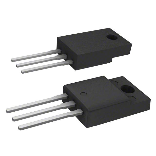
The STF3HNK90Z is an N-Channel MOSFET manufactured by STMicroelectronics, rated for 800 V drain-to-source voltage with 3 A continuous drain current at 25°C. The device is housed in a TO-220FP through-hole package and is part of the SuperMESH™ series. This part is classified as obsolete, making identification of equivalent and substitute components necessary for ongoing design support and production continuity. Substitute parts must maintain electrical compatibility across critical parameters including voltage rating, current capacity, and thermal characteristics while accommodating available packaging options.
Substiute Parts
Key Parameters
| Parameter | STF3HNK90Z | Unit |
|---|---|---|
| Drain-to-Source Voltage (Vdss) | 800 | V |
| Continuous Drain Current (Id) @ 25°C | 3 | A |
| On-State Resistance (Rds On) @ 1.5A, 10V | 4.2 | Ω |
| Gate Threshold Voltage (Vgs(th)) @ 50µA | 4.5 | V |
| Gate Charge (Qg) @ 10V | 35 | nC |
| Power Dissipation (Max) | 25 | W |
| Operating Temperature Range | -55 to 150 | °C |
| Package Type | TO-220FP | — |
| Product Status | Obsolete | — |
Substitute Part Grouping Explanation
Substitution eligibility is determined by the following critical parameters:
Voltage Compatibility: All substitute parts must support the application voltage requirement. The main part operates at 800 V Vdss. Substitute parts rated at 800 V or higher are electrically compatible for voltage stress conditions.
Current Capacity: The main part delivers 3 A continuous drain current. Substitute parts rated at 3 A or higher satisfy current delivery requirements without derating.
On-State Resistance (Rds On): This parameter directly affects power dissipation and thermal performance. Lower Rds On values indicate improved efficiency and reduced heat generation.
Gate Charge (Qg): Lower gate charge values reduce switching losses and gate drive power requirements, improving overall circuit efficiency.
Thermal Rating: Power dissipation capability must meet or exceed the application's thermal demands. The main part is rated for 25 W at Tc.
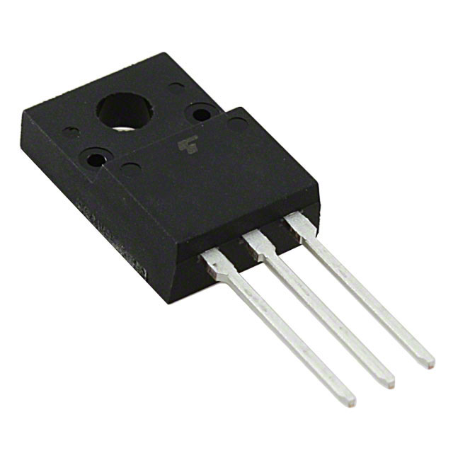
Package and Mounting: Through-hole TO-220 variants (TO-220FP, TO-220SIS, TO-220F) are mechanically compatible with standard PCB layouts designed for the original part.
Compliance Status: RoHS3 compliance and REACH unaffected status ensure regulatory alignment for current manufacturing and distribution.
Parameter Comparison
| Parameter | STF3HNK90Z | STP4NK80ZFP | 2SK3564(STA4,Q,M) | 2SK3565(Q,M) | FQPF4N90C | IRFIBF30GPBF | Unit |
|---|---|---|---|---|---|---|---|
| Manufacturer | STMicroelectronics | STMicroelectronics | Toshiba | Toshiba | onsemi | Vishay Siliconix | — |
| Vdss | 800 | 800 | 900 | 900 | 900 | 900 | V |
| Id @ 25°C | 3 | 3 | 3 | 5 | 4 | 1.9 | A |
| Rds On (Max) @ 10V | 4.2 | 3.5 | 4.3 | 2.5 | 4.2 | 3.7 | Ω |
| Vgs(th) (Max) | 4.5 | 4.5 | 4 | 4 | 5 | 4 | V |
| Qg (Max) @ 10V | 35 | 22.5 | 17 | 28 | 22 | 78 | nC |
| Ciss (Max) @ 25V | 690 | 575 | 700 | 1150 | 960 | 1200 | pF |
| Power Dissipation (Max) | 25 | 25 | 40 | 45 | 47 | 35 | W |
| Operating Temperature | -55 to 150 | -55 to 150 | to 150 | to 150 | -55 to 150 | -55 to 150 | °C |
| Package | TO-220FP | TO-220FP | TO-220SIS | TO-220SIS | TO-220F-3 | TO-220-3 | — |
| Product Status | Obsolete | Active | Active | Active | Active | Active | — |
| RoHS Status | ROHS3 Compliant | ROHS3 Compliant | ROHS3 Compliant | RoHS Compliant | ROHS3 Compliant | ROHS3 Compliant | — |
Engineering Selection Recommendations
Primary Substitute: STP4NK80ZFP
The STP4NK80ZFP is the direct equivalent from STMicroelectronics. It maintains identical voltage (800 V) and current (3 A) ratings, operates across the same temperature range (-55°C to 150°C), and uses the same TO-220FP package. The STP4NK80ZFP exhibits improved electrical performance with lower on-state resistance (3.5 Ω versus 4.2 Ω) and reduced gate charge (22.5 nC versus 35 nC), resulting in lower power dissipation and improved switching efficiency. Product status is active with full RoHS3 compliance. This part is the preferred choice for direct replacement in existing designs.
Secondary Substitutes: 2SK3564(STA4,Q,M) and FQPF4N90C
Both parts operate at 900 V, providing 100 V additional voltage margin over the original 800 V specification. The 2SK3564 maintains the 3 A current rating with comparable on-state resistance (4.3 Ω) and enhanced power dissipation capability (40 W). The FQPF4N90C provides 4 A current capacity with 47 W power dissipation, offering additional design margin. Both parts are active products with full compliance certifications. Package variants (TO-220SIS and TO-220F-3) are mechanically compatible with standard TO-220 footprints.
Alternative Substitute: 2SK3565(Q,M)
The 2SK3565 operates at 900 V with 5 A continuous current and 45 W power dissipation, providing significant performance headroom. On-state resistance is reduced to 2.5 Ω, enabling lower thermal stress in high-current applications. This part is suitable for designs requiring enhanced current capacity or thermal performance beyond the original specification.
Not Recommended: IRFIBF30GPBF
The IRFIBF30GPBF is rated for only 1.9 A continuous current, which is below the 3 A requirement of the original part. Although it operates at 900 V and maintains compliance certifications, the reduced current capacity makes it unsuitable for direct substitution in applications requiring the full 3 A rating.
Frequently Asked Questions (FAQ)
Q: Can the STP4NK80ZFP directly replace the STF3HNK90Z in existing PCB designs?
A: Yes. The STP4NK80ZFP is pin-compatible and uses the same TO-220FP package. Electrical parameters are equivalent or superior, with no circuit modifications required. The part is a direct drop-in replacement.
Q: What is the advantage of using a 900 V rated part in an 800 V application?
A: A 900 V rated device provides 100 V additional voltage margin, improving reliability under transient overvoltage conditions. This margin is particularly beneficial in applications with switching transients or supply voltage spikes. The trade-off is typically higher on-state resistance at the same current level.
Q: Are TO-220SIS and TO-220F packages mechanically compatible with TO-220FP footprints?
A: TO-220 variants (TO-220FP, TO-220SIS, TO-220F-3) share identical pin spacing and mounting hole patterns. They are mechanically interchangeable on standard PCB layouts. However, thermal performance may vary due to differences in tab isolation and heat transfer characteristics. Verify thermal requirements for your specific application.
Q: Why does the IRFIBF30GPBF appear in the substitute list if it has lower current capacity?
A: The IRFIBF30GPBF is listed as a substitute option for applications where continuous drain current does not exceed 1.9 A. It is not suitable for designs requiring the full 3 A rating of the original part. Current capacity must be verified against application requirements before selection.
Q: What is the significance of gate charge (Qg) differences between substitute parts?
A: Gate charge directly affects switching losses and gate drive power requirements. Lower gate charge (STP4NK80ZFP at 22.5 nC, 2SK3564 at 17 nC) reduces switching losses and simplifies gate drive circuit design. Higher gate charge (IRFIBF30GPBF at 78 nC) increases gate drive power and switching losses, potentially requiring more robust gate drive circuitry.
Q: Are all substitute parts RoHS3 compliant?
A: Yes. All active substitute parts listed (STP4NK80ZFP, 2SK3564, 2SK3565, FQPF4N90C, IRFIBF30GPBF) carry RoHS3 compliance certification, ensuring regulatory alignment with current manufacturing and distribution requirements.
Q: Which substitute part offers the best thermal performance?
A: The 2SK3565(Q,M) provides the highest power dissipation rating at 45 W with the lowest on-state resistance at 2.5 Ω. The FQPF4N90C offers 47 W dissipation capability. Both parts are suitable for thermally demanding applications. Selection depends on current requirements and available board space for thermal management.
Q: Can I use a substitute part with higher current rating in a lower-current application?
A: Yes. A part rated for higher current (such as 2SK3565 at 5 A) can be used in applications requiring lower current (3 A). The device will operate within its safe operating area with reduced stress. Verify that the package and thermal characteristics are compatible with your PCB layout and cooling strategy.
Alternative Parts

SJ6012L2TP
Littelfuse Inc.
6 Alternative Parts

JMK107BBJ476MA-RE
Taiyo Yuden
10 Alternative Parts

GMK107BBJ475MA-T
Taiyo Yuden
5 Alternative Parts
SJ6020N2ARP
Littelfuse Inc.
3 Alternative Parts
SJ6025R2ATP
Littelfuse Inc.
4 Alternative Parts

2474-05L
API Delevan Inc.
1 Alternative Parts

4590R-684K
API Delevan Inc.
1 Alternative Parts

CM6560R-334
API Delevan Inc.
1 Alternative Parts

CM6460-104
API Delevan Inc.
1 Alternative Parts

5526-12
API Delevan Inc.
1 Alternative Parts