


Request Quote
(Ships tomorrow)
STF11N50M2 Equivalent & Substitute Parts
Part Overview
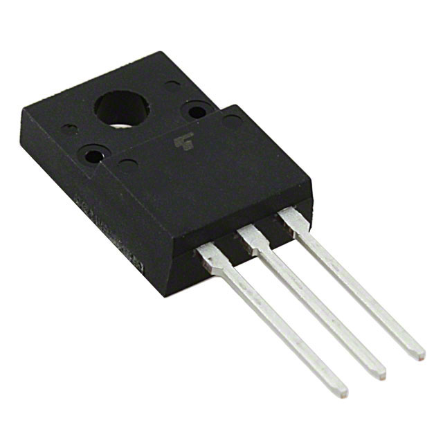
The STF11N50M2 is an N-Channel 500V 8A MOSFET manufactured by STMicroelectronics in the MDmesh™ II Plus series. This device is packaged in TO-220FP and rated for 25W power dissipation with an operating temperature range of -55°C to 150°C. The part is currently listed as obsolete, making identification of functionally equivalent alternatives necessary for ongoing design support and procurement continuity.
Substiute Parts
Key Parameters
| Parameter | Value | Unit |
|---|---|---|
| Drain to Source Voltage (Vdss) | 500 | V |
| Continuous Drain Current (Id) @ 25°C | 8 | A |
| Rds On (Max) @ 4A, 10V | 530 | mOhm |
| Gate Threshold Voltage (Vgs(th)) @ 250µA | 4 | V |
| Gate Charge (Qg) @ 10V | 12 | nC |
| Power Dissipation (Max) | 25 | W |
| Operating Temperature Range | -55 to 150 | °C |
| Package Type | TO-220FP | — |
| FET Type | N-Channel Enhancement Mode | — |
Substitute Part Grouping Explanation
Substitution of the STF11N50M2 is determined by the following critical parameters:
Voltage Rating: All substitute parts must maintain a Drain to Source Voltage (Vdss) of 500V or higher to ensure safe operation in the original application circuit.
Current Capability: The continuous drain current (Id) must be equal to or greater than 8A at 25°C to support the same load conditions.
On-State Resistance (Rds On): The maximum on-state resistance should be comparable to or lower than 530mOhm to maintain similar power dissipation characteristics and thermal performance.
Package Compatibility: The substitute must be compatible with TO-220 family packages (TO-220FP, TO-220-3, TO-220FL, TO-220SIS) to ensure mechanical fit in the original PCB layout.
Operating Temperature: The device must support the full operating range of -55°C to 150°C or a subset thereof that covers the application requirements.
Regulatory Compliance: All substitute parts must maintain RoHS3 compliance and appropriate REACH status for the target market.
Parameter Comparison
| Part Number | Manufacturer | Vdss (V) | Id @ 25°C (A) | Rds On Max (mOhm) | Qg @ 10V (nC) | Power Dissipation (W) | Temp Range (°C) | Package | Status |
|---|---|---|---|---|---|---|---|---|---|
| STF11N50M2 | STMicroelectronics | 500 | 8 | 530 | 12 | 25 | -55 to 150 | TO-220FP | Obsolete |
| IPA50R500CEXKSA2 | Infineon Technologies | 500 | 5.4 | 500 | 18.7 | 28 | -40 to 150 | PG-TO220-3-FP | Active |
| IXFP12N50P | IXYS | 500 | 12 | 500 | 29 | 200 | -55 to 150 | TO-220-3 | Active |
| IXTP12N50P | IXYS | 500 | 12 | 500 | 29 | 200 | -55 to 150 | TO-220-3 | Active |
| IXTP12N50PM | IXYS | 500 | 6 | 500 | 29 | 50 | -55 to 150 | TO-220-3 | Active |
| IXTP15N50L2 | IXYS | 500 | 15 | 480 | 123 | 300 | -55 to 150 | TO-220-3 | Active |
| IXTP6N50D2 | IXYS | 500 | 6 | 500 | 96 | 300 | -55 to 150 | TO-220-3 | Active |
| RJK4007DPP-M0#T2 | Renesas Electronics | 400 | 7.6 | 550 | 24.5 | 32 | -55 to 150 | TO-220FL | Active |
| TK12A45D(STA4,Q,M) | Toshiba Semiconductor | 450 | 12 | 520 | 24 | 45 | -55 to 150 | TO-220SIS | Active |
| TK12A53D(STA4,Q,M) | Toshiba Semiconductor | 525 | 12 | 580 | 25 | 45 | -55 to 150 | TO-220SIS | Active |
Engineering Selection Recommendations
Primary Substitutes (500V Vdss Rating):
The IXFP12N50P and IXTP12N50P from IXYS are direct voltage and package-compatible alternatives. Both devices maintain the 500V Vdss rating, exceed the 8A current requirement at 12A, and are rated for -55°C to 150°C operation. These parts are active products with full RoHS3 compliance. The higher current rating and power dissipation capability (200W) provide design margin for thermal management.
The IXTP15N50L2 offers the highest current capability at 15A with superior on-state resistance (480mOhm) and is suitable for applications requiring additional current headroom. This part is active and fully compliant.
Secondary Substitutes (Reduced Voltage Rating):
The TK12A53D(STA4,Q,M) from Toshiba provides 525V Vdss, exceeding the original 500V specification, with 12A current capability and comparable on-state resistance (580mOhm). This part is active and maintains the full temperature range.
The TK12A45D(STA4,Q,M) operates at 450V Vdss, which is below the original specification. This part is suitable only for applications where the circuit voltage does not exceed 450V.
The RJK4007DPP-M0#T2 from Renesas operates at 400V Vdss and is not recommended as a direct substitute due to the voltage derating.
Voltage-Constrained Applications:
The IPA50R500CEXKSA2 from Infineon maintains 500V Vdss but provides only 5.4A continuous current, which is below the 8A requirement. This part is suitable only for applications with reduced current demands.
All recommended substitutes are active products with RoHS3 compliance and appropriate regulatory certifications for industrial and commercial applications.
Frequently Asked Questions (FAQ)
Q: Can the IXTP12N50P directly replace the STF11N50M2 in my circuit?
A: Yes, the IXTP12N50P is electrically compatible. Both devices share the same 500V Vdss rating, TO-220 package family, and -55°C to 150°C operating temperature range. The IXTP12N50P provides higher current capability (12A vs. 8A) and greater power dissipation rating (200W vs. 25W), making it suitable for the same application with additional thermal margin. Pin configuration must be verified against the specific TO-220 variant used in your design.
Q: What is the difference between IXFP12N50P and IXTP12N50P?
A: Both parts share identical electrical specifications: 500V Vdss, 12A continuous current, 500mOhm on-state resistance, and -55°C to 150°C operating range. The primary difference is the series designation (HiPerFET™ Polar vs. Polar) and internal device architecture. Both are active products suitable for direct substitution of the STF11N50M2.
Q: Why does the IPA50R500CEXKSA2 have lower current rating than the STF11N50M2?
A: The IPA50R500CEXKSA2 is rated for 5.4A continuous current, which is below the STF11N50M2 specification of 8A. This part is from the CoolMOS™ CE series and is optimized for different application requirements. It is suitable only for circuits requiring less than 5.4A continuous drain current.
Q: Can I use the TK12A45D in place of the STF11N50M2?
A: The TK12A45D operates at 450V Vdss, which is 50V below the STF11N50M2 specification. This part is suitable only if your circuit operates at voltages not exceeding 450V. If your application requires the full 500V rating, use parts with 500V or higher Vdss specification.
Q: Are all substitute parts RoHS3 compliant?
A: Yes, all substitute parts listed in this document are RoHS3 compliant. The STF11N50M2 is also RoHS3 compliant. Verify REACH status with your supplier for specific regional requirements.
Q: What is the significance of the on-state resistance (Rds On) difference between parts?
A: On-state resistance directly affects power dissipation and thermal performance. The STF11N50M2 has 530mOhm Rds On at 4A, 10V. Most substitute parts maintain 500mOhm or lower, resulting in lower power dissipation and reduced heat generation. Lower Rds On values improve efficiency in switching applications.
Q: Can I use IXTP15N50L2 in a space-constrained design?
A: The IXTP15N50L2 uses the same TO-220-3 package as other substitutes, so mechanical fit is identical. However, this part has significantly higher gate charge (123nC vs. 12nC in the original), which may require gate driver circuit adjustments. Verify gate drive capability before selection.
Q: What package variants are available among the substitutes?
A: Substitute parts use TO-220 family packages: TO-220-3, TO-220FP, TO-220FL, and TO-220SIS. All variants are mechanically compatible with standard TO-220 PCB footprints, though pin spacing and lead configuration should be verified for your specific layout. The TO-220FP and TO-220-3 Full Pack variants are most common.
Alternative Parts

SJ6012L2TP
Littelfuse Inc.
6 Alternative Parts

JMK107BBJ476MA-RE
Taiyo Yuden
10 Alternative Parts

GMK107BBJ475MA-T
Taiyo Yuden
5 Alternative Parts
SJ6020N2ARP
Littelfuse Inc.
3 Alternative Parts
SJ6025R2ATP
Littelfuse Inc.
4 Alternative Parts

2474-05L
API Delevan Inc.
1 Alternative Parts

4590R-684K
API Delevan Inc.
1 Alternative Parts

CM6560R-334
API Delevan Inc.
1 Alternative Parts

CM6460-104
API Delevan Inc.
1 Alternative Parts

5526-12
API Delevan Inc.
1 Alternative Parts