


Request Quote
(Ships tomorrow)
STB75NF75LT4 Equivalent & Substitute Parts
Part Overview
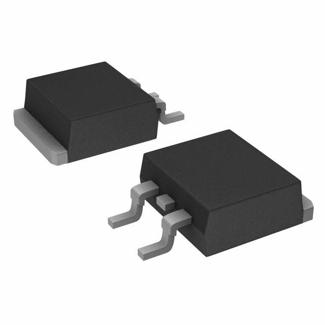
The STB75NF75LT4 is an N-Channel MOSFET manufactured by STMicroelectronics in the STripFET™ II series. This device operates at 75 V drain-to-source voltage with 75 A continuous drain current and 300 W maximum power dissipation in a surface mount D2PAK package. The part is Active status and ROHS3 compliant with unlimited moisture sensitivity rating.
Substitute parts are necessary when the primary part becomes unavailable, when alternative packaging formats are required, or when design optimization calls for different electrical characteristics within compatible parameter ranges. All substitute parts listed maintain the same package type (D2PAK/TO-263-3) and core voltage/current specifications to ensure direct functional replacement.
Substiute Parts
Key Parameters
| Parameter | Value | Unit |
|---|---|---|
| Drain to Source Voltage (Vdss) | 75 | V |
| Continuous Drain Current (Id) @ 25°C | 75 | A (Tc) |
| Rds On (Max) @ Id, Vgs | 11 | mOhm @ 37.5A, 10V |
| Gate Threshold Voltage (Vgs(th)) @ Id | 2.5 | V @ 250µA |
| Power Dissipation (Max) | 300 | W (Tc) |
| Operating Temperature Range | -55 to 175 | °C (TJ) |
| Package Type | D2PAK (TO-263-3) | Surface Mount |
| FET Type | N-Channel | MOSFET |
Substitute Part Grouping Explanation
Substitute parts for the STB75NF75LT4 are classified based on electrical parameter compatibility within the following criteria:
Direct Substitutes (Electrical Equivalents): Parts maintaining 75 V Vdss, 75 A continuous drain current, 300 W power dissipation, and D2PAK package configuration.
Functional Substitutes (Parameter Variants): Parts with 75 V Vdss and D2PAK package but with variations in continuous drain current (67 A to 120 A), power dissipation (157 W to 310 W), or on-resistance characteristics. These parts are suitable when the application can tolerate different current ratings or thermal performance.
Voltage-Reduced Substitutes: Parts with lower Vdss ratings (55 V to 60 V) in D2PAK package. These are suitable only for applications where the lower voltage rating meets design requirements.
The following electrical parameters determine substitution eligibility:
- Drain-to-Source Voltage (Vdss): 75 V (primary requirement)
- Package Type: D2PAK/TO-263-3 (mandatory for direct replacement)
- Continuous Drain Current: 75 A minimum (for direct equivalence)
- Operating Temperature Range: -55°C to 175°C (standard requirement)
- Surface Mount Technology: Required
Parameter Comparison
| Part Number | Manufacturer | Vdss (V) | Id @ 25°C (A) | Rds On (mOhm) | Power Diss. (W) | Package | Status |
|---|---|---|---|---|---|---|---|
| STB75NF75LT4 | STMicroelectronics | 75 | 75 | 11 @ 37.5A, 10V | 300 | D2PAK | Active |
| BUK9606-75B,118 | Nexperia USA Inc. | 75 | 75 | 5.5 @ 25A, 10V | 300 | D2PAK | Active |
| BUK9609-75A,118 | NXP USA Inc. | 75 | 75 | 8.5 @ 25A, 10V | 230 | D2PAK | Active |
| BUK9616-75B,118 | Nexperia USA Inc. | 75 | 67 | 14 @ 25A, 10V | 157 | D2PAK | Active |
| FDB045AN08A0 | onsemi | 75 | 90 | 4.5 @ 80A, 10V | 310 | D2PAK | Active |
| FDB060AN08A0 | onsemi | 75 | 80 | 6 @ 80A, 10V | 255 | D2PAK | Active |
| FDB088N08 | onsemi | 75 | 120 | 8.8 @ 75A, 10V | 160 | D2PAK | Active |
| IPB80N06S209ATMA2 | Infineon Technologies | 55 | 80 | 8.8 @ 50A, 10V | 190 | D2PAK | Active |
| IPB80N08S207ATMA1 | Infineon Technologies | 75 | 80 | 7.1 @ 80A, 10V | 300 | D2PAK | Active |
| IPB80N08S2L07ATMA1 | Infineon Technologies | 75 | 80 | 6.8 @ 80A, 10V | 300 | D2PAK | Active |
| IRF1010ESTRLPBF | Infineon Technologies | 60 | 84 | 12 @ 50A, 10V | 200 | D2PAK | Active |
Engineering Selection Recommendations
Direct Electrical Equivalents (Recommended for Pin-Compatible Replacement):
BUK9606-75B,118 (Nexperia) and IPB80N08S207ATMA1 (Infineon) maintain identical 75 V / 75 A specifications with 300 W power dissipation. Both parts are Active status with ROHS3 compliance. BUK9606-75B,118 includes AEC-Q101 automotive qualification. IPB80N08S207ATMA1 is part of the OptiMOS™ series with improved on-resistance characteristics (7.1 mOhm vs. 11 mOhm).
Functional Alternatives (Higher Current Capability):
FDB045AN08A0 and FDB060AN08A0 (onsemi PowerTrench® series) provide 90 A and 80 A continuous drain current respectively, with superior on-resistance performance. These parts are suitable when thermal headroom or current margin is required. FDB088N08 offers 120 A continuous current with lower power dissipation (160 W), appropriate for high-current applications with reduced thermal requirements.
Voltage-Reduced Alternative (Lower Voltage Applications Only):
IPB80N06S209ATMA2 operates at 55 V Vdss with 80 A continuous current. This part is suitable only for applications where the lower voltage rating is acceptable and provides cost optimization for reduced voltage designs.
Packaging Considerations:
All substitute parts maintain D2PAK (TO-263-3) surface mount package configuration. Tape & Reel (TR) packaging is available for BUK9606-75B,118, BUK9609-75A,118, FDB060AN08A0, and Infineon OptiMOS™ series parts. Cut Tape (CT) & Digi-Reel® packaging is available for FDB045AN08A0, FDB088N08, and IRF1010ESTRLPBF.
Compliance Status:
All listed substitute parts are ROHS3 compliant with unlimited moisture sensitivity (MSL 1). Nexperia BUK series parts include AEC-Q101 automotive qualification. Infineon OptiMOS™ series parts are qualified for automotive applications. onsemi PowerTrench® series parts are Active status with full compliance documentation.
Frequently Asked Questions (FAQ)
Q: Can BUK9606-75B,118 replace STB75NF75LT4 in all applications?
A: BUK9606-75B,118 is a direct electrical equivalent with identical 75 V / 75 A / 300 W specifications and D2PAK package. The primary difference is improved on-resistance (5.5 mOhm vs. 11 mOhm), which reduces power dissipation and heat generation. This part is suitable for direct replacement in all applications where the STB75NF75LT4 is specified.
Q: What is the difference between continuous drain current ratings (Id @ 25°C vs. Tc)?
A: Continuous drain current is specified at two conditions. Id @ 25°C (Ta) represents ambient temperature operation, while Id @ Tc represents case temperature operation. The Tc rating is typically higher and represents the maximum current the device can sustain with proper thermal management. For the STB75NF75LT4, the 75 A rating is specified at Tc (case temperature).
Q: Can I use FDB088N08 (120 A) instead of STB75NF75LT4 (75 A)?
A: FDB088N08 is electrically compatible with 75 V Vdss and D2PAK package. The higher 120 A continuous current rating provides additional current margin. However, the lower power dissipation rating (160 W vs. 300 W) indicates different thermal characteristics. This part is suitable when the application requires higher current capability and can operate within the 160 W thermal budget.
Q: Why does IPB80N06S209ATMA2 have a lower voltage rating (55 V)?
A: IPB80N06S209ATMA2 is rated for 55 V Vdss, which is 20 V lower than the STB75NF75LT4. This part is not a direct substitute for 75 V applications. It is suitable only for designs where the lower voltage rating meets system requirements, such as lower voltage power supplies or battery-powered applications.
Q: What packaging options are available for substitute parts?
A: Substitute parts are available in multiple packaging formats. Tape & Reel (TR) packaging is standard for high-volume production and automated assembly. Cut Tape (CT) & Digi-Reel® packaging is available for lower-volume requirements. All parts maintain the same D2PAK (TO-263-3) physical package for PCB compatibility.
Q: Are automotive-qualified alternatives available?
A: Yes. BUK9606-75B,118 and BUK9609-75A,118 (Nexperia) include AEC-Q101 automotive qualification. Infineon OptiMOS™ series parts (IPB80N08S207ATMA1, IPB80N08S2L07ATMA1) are qualified for automotive applications. These parts are suitable for automotive and industrial applications requiring qualification documentation.
Q: How do on-resistance differences affect circuit performance?
A: On-resistance (Rds On) directly affects power dissipation and heat generation. Lower on-resistance reduces I²R losses. BUK9606-75B,118 (5.5 mOhm) dissipates less heat than STB75NF75LT4 (11 mOhm) at the same current. FDB045AN08A0 (4.5 mOhm) provides the lowest on-resistance among 75 V alternatives. Higher on-resistance parts (BUK9616-75B,118 at 14 mOhm) require additional thermal management.
Q: What is the significance of gate charge (Qg) differences?
A: Gate charge affects switching speed and driver circuit requirements. Higher gate charge requires more driver current or longer switching times. STB75NF75LT4 specifies 90 nC @ 5 V, while IPB80N08S207ATMA1 specifies 180 nC @ 10 V. Lower gate charge (BUK9616-75B,118 at 35 nC) enables faster switching with simpler driver circuits.
Q: Can I mix different substitute parts in the same circuit?
A: All listed substitute parts maintain D2PAK package compatibility and can be mounted in the same PCB footprint. However, electrical parameter differences (on-resistance, gate charge, input capacitance) may affect circuit performance. Designs should be validated for each specific part selection to ensure proper operation and thermal management.
Alternative Parts

SJ6012L2TP
Littelfuse Inc.
6 Alternative Parts

JMK107BBJ476MA-RE
Taiyo Yuden
10 Alternative Parts

GMK107BBJ475MA-T
Taiyo Yuden
5 Alternative Parts
SJ6020N2ARP
Littelfuse Inc.
3 Alternative Parts
SJ6025R2ATP
Littelfuse Inc.
4 Alternative Parts

2474-05L
API Delevan Inc.
1 Alternative Parts

4590R-684K
API Delevan Inc.
1 Alternative Parts

CM6560R-334
API Delevan Inc.
1 Alternative Parts

CM6460-104
API Delevan Inc.
1 Alternative Parts

5526-12
API Delevan Inc.
1 Alternative Parts