


Request Quote
(Ships tomorrow)
STB45NF06T4 Equivalent & Substitute Parts
Part Overview
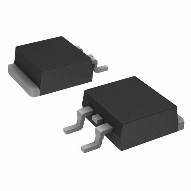
The STB45NF06T4 is an N-Channel MOSFET manufactured by STMicroelectronics, rated for 60V drain-to-source voltage and 38A continuous drain current at 25°C. This device operates in the STripFET™ II series and is housed in a D2PAK (TO-263-4) surface mount package. The part is currently in Active product status with 6100 units in stock.
Substitute parts are necessary when the primary device becomes unavailable, when design requirements demand alternative electrical characteristics, or when supply chain constraints require qualified alternatives. The following substitute devices maintain compatibility within the specified electrical and mechanical parameters while offering equivalent or enhanced performance characteristics.
Substiute Parts
Key Parameters
| Parameter | Value | Unit |
|---|---|---|
| Drain-to-Source Voltage (Vdss) | 60 | V |
| Continuous Drain Current (Id) @ 25°C | 38 | A |
| On-State Resistance (Rds On) @ 19A, 10V | 28 | mOhm |
| Gate-Source Threshold Voltage (Vgs(th)) @ 250µA | 4 | V |
| Gate Charge (Qg) @ 10V | 58 | nC |
| Input Capacitance (Ciss) @ 25V | 1730 | pF |
| Power Dissipation (Max) | 80 | W |
| Operating Temperature (TJ) | 175 | °C |
| Package Type | D2PAK (TO-263-4) | - |
| Mounting Type | Surface Mount | - |
| RoHS Status | ROHS3 Compliant | - |
| Moisture Sensitivity Level | 1 (Unlimited) | - |
Substitute Part Grouping Explanation
Substitution eligibility for the STB45NF06T4 is determined by the following critical parameters:
Voltage Rating: Substitute devices must maintain a Vdss rating of 60V or higher to ensure safe operation within the same voltage domain.
Current Rating: Substitute devices must support a continuous drain current (Id) of 38A or greater at 25°C to handle equivalent or higher load conditions.
On-State Resistance (Rds On): Lower Rds On values indicate improved efficiency and reduced power dissipation. Substitute devices with Rds On values at or below 28mOhm @ 10V gate drive are considered equivalent or superior.
Package Compatibility: All substitute devices must use the D2PAK (TO-263) surface mount package to ensure mechanical and thermal compatibility with existing PCB layouts.
Gate Drive Voltage: Substitute devices must operate with standard 10V gate drive voltage to maintain compatibility with existing gate driver circuits.
Threshold Voltage (Vgs(th)): Substitute devices must maintain a threshold voltage of 4V @ 250µA to ensure consistent switching behavior.
Compliance: All substitute devices must maintain ROHS3 compliance and MSL 1 rating to meet environmental and handling requirements.
Parameter Comparison
| Part Number | Manufacturer | Vdss (V) | Id @ 25°C (A) | Rds On (mOhm) | Vgs(th) (V) | Qg (nC) | Ciss (pF) | Power Dissipation (W) | Package | Status |
|---|---|---|---|---|---|---|---|---|---|---|
| STB45NF06T4 | STMicroelectronics | 60 | 38 | 28 @ 19A, 10V | 4 @ 250µA | 58 @ 10V | 1730 @ 25V | 80 | D2PAK (TO-263-4) | Active |
| IRFZ44SPBF | Vishay Siliconix | 60 | 50 | 28 @ 31A, 10V | 4 @ 250µA | 67 @ 10V | 1900 @ 25V | 150 | D2PAK (TO-263-3) | Active |
| IRFZ44STRLPBF | Vishay Siliconix | 60 | 50 | 28 @ 31A, 10V | 4 @ 250µA | 67 @ 10V | 1900 @ 25V | 150 | D2PAK (TO-263-3) | Active |
| IRFZ44NSTRLPBF | Infineon Technologies | 55 | 49 | 17.5 @ 25A, 10V | 4 @ 250µA | 63 @ 10V | 1470 @ 25V | 94 | D2PAK (TO-263-3) | Active |
| IRFZ44ESTRLPBF | Infineon Technologies | 60 | 48 | 23 @ 29A, 10V | 4 @ 250µA | 60 @ 10V | 1360 @ 25V | 110 | D2PAK (TO-263-3) | Not For New Designs |
| IRFZ44ZSTRRPBF | Infineon Technologies | 55 | 51 | 13.9 @ 31A, 10V | 4 @ 250µA | 43 @ 10V | 1420 @ 25V | 80 | D2PAK (TO-263-3) | Not For New Designs |
| IRFZ46NSTRLPBF | Infineon Technologies | 55 | 53 | 16.5 @ 28A, 10V | 4 @ 250µA | 72 @ 10V | 1696 @ 25V | 107 | D2PAK (TO-263-3) | Not For New Designs |
| IRFZ48RSPBF | Vishay Siliconix | 60 | 50 | 18 @ 43A, 10V | 4 @ 250µA | 110 @ 10V | 2400 @ 25V | 190 | D2PAK (TO-263-3) | Active |
| IRLZ44SPBF | Vishay Siliconix | 60 | 50 | 28 @ 31A, 5V | 2 @ 250µA | 66 @ 5V | 3300 @ 25V | 150 | D2PAK (TO-263-3) | Active |
| IRFZ34NSTRLPBF | Infineon Technologies | 55 | 29 | 40 @ 16A, 10V | 4 @ 250µA | 34 @ 10V | 700 @ 25V | 68 | D2PAK (TO-263-3) | Active |
| BUK7635-55A,118 | Nexperia USA Inc. | 55 | 35 | 35 @ 20A, 10V | 4 @ 1mA | - | 872 @ 25V | 85 | D2PAK (TO-263-3) | Obsolete |
Engineering Selection Recommendations
Primary Substitutes (Active Status, Recommended for New Designs)
IRFZ44SPBF and IRFZ44STRLPBF are direct functional equivalents with identical 60V/50A ratings and matching Rds On characteristics. Both devices are in Active product status and ROHS3 compliant. The primary difference is packaging format: IRFZ44SPBF is supplied in Tube packaging, while IRFZ44STRLPBF is supplied in Tape & Reel format. These devices provide superior current handling (50A vs. 38A) and higher power dissipation capability (150W vs. 80W), making them suitable for applications requiring enhanced thermal performance.
IRFZ44NSTRLPBF is an Active-status alternative with 55V rating and 49A continuous current. This device features superior on-state resistance (17.5mOhm vs. 28mOhm), resulting in lower power dissipation and improved efficiency. The 55V rating is acceptable for applications where the 60V specification provides design margin.
IRFZ48RSPBF is an Active-status device with 60V rating and 50A current capability. This device features the lowest on-state resistance (18mOhm) among available substitutes, providing optimal efficiency. Higher gate charge (110nC) and input capacitance (2400pF) require verification of gate driver capability.
IRLZ44SPBF is an Active-status device with 60V/50A ratings and low threshold voltage (2V). This device operates with 4V/5V gate drive voltage rather than 10V, requiring gate driver circuit compatibility verification. Lower Vgs(th) enables faster switching transitions.
Secondary Substitutes (Not For New Designs)
IRFZ44ESTRLPBF, IRFZ44ZSTRRPBF, and IRFZ46NSTRLPBF are classified as "Not For New Designs" and are suitable only for replacement applications in existing systems. These devices remain available in inventory but are not recommended for new product development.
Not Recommended
BUK7635-55A,118 is classified as Obsolete and should not be selected for new applications. IRFZ34NSTRLPBF has reduced current rating (29A) below the STB45NF06T4 specification and is not suitable as a direct substitute.
Frequently Asked Questions (FAQ)
Q: Can IRFZ44SPBF directly replace STB45NF06T4 in existing designs?
A: IRFZ44SPBF is mechanically and electrically compatible with STB45NF06T4. Both devices use D2PAK surface mount packages and operate at 60V with matching gate drive voltage (10V). The higher current rating (50A vs. 38A) and improved thermal performance (150W vs. 80W) make IRFZ44SPBF suitable for direct substitution. Verify PCB layout compatibility with the specific D2PAK variant (TO-263-3 vs. TO-263-4 lead configuration).
Q: What is the difference between IRFZ44SPBF and IRFZ44STRLPBF?
A: These devices are electrically identical with matching electrical specifications. The primary difference is packaging format: IRFZ44SPBF is supplied in Tube packaging for manual handling and small-volume applications, while IRFZ44STRLPBF is supplied in Tape & Reel format for automated assembly. Both are Active-status products suitable for new designs.
Q: Why does IRFZ44NSTRLPBF have a lower voltage rating (55V vs. 60V)?
A: IRFZ44NSTRLPBF is rated for 55V maximum drain-to-source voltage, compared to 60V for STB45NF06T4. This device is suitable for applications where the circuit voltage does not exceed 55V. The lower voltage rating enables superior on-state resistance (17.5mOhm vs. 28mOhm), resulting in reduced power dissipation and improved efficiency. Verify that the application voltage margin accommodates the 55V specification.
Q: Is IRLZ44SPBF compatible with existing gate driver circuits?
A: IRLZ44SPBF operates with 4V/5V gate drive voltage, compared to 10V for STB45NF06T4. This device features lower threshold voltage (2V vs. 4V) and requires gate driver circuits capable of 5V output. Existing 10V gate driver circuits may not provide optimal switching performance with IRLZ44SPBF. Verify gate driver compatibility before substitution.
Q: Can I use IRFZ34NSTRLPBF as a substitute?
A: IRFZ34NSTRLPBF is not recommended as a direct substitute. This device has a continuous drain current rating of 29A, which is below the STB45NF06T4 specification of 38A. Use of this device in applications requiring 38A operation would exceed the device rating and create reliability risk.
Q: What is the significance of "Not For New Designs" status?
A: Devices marked "Not For New Designs" are available for replacement and repair of existing systems but are not recommended for new product development. These devices may have limited long-term availability or may be superseded by newer alternatives. For new designs, select devices with Active product status.
Q: Are all substitute parts ROHS3 compliant?
A: All substitute parts listed in this reference are ROHS3 compliant and maintain MSL 1 (Unlimited) moisture sensitivity rating, matching the environmental compliance of STB45NF06T4. Verify compliance documentation for specific procurement requirements.
Q: What is the impact of different on-state resistance values?
A: On-state resistance (Rds On) directly affects power dissipation and thermal performance. Lower Rds On values reduce I²R losses during conduction. For example, IRFZ44NSTRLPBF (17.5mOhm) dissipates less power than STB45NF06T4 (28mOhm) at equivalent current levels. Higher Rds On values increase power dissipation and require enhanced thermal management. Select devices based on thermal budget and efficiency requirements.
Q: Can I mix different substitute parts in the same circuit?
A: All substitute parts are mechanically and electrically compatible for parallel operation in the same circuit. However, verify that gate drive circuits provide adequate current to drive all devices simultaneously. Devices with different threshold voltages or gate charge characteristics may exhibit unequal current sharing. Consult application-specific design guidelines for parallel device operation.
Alternative Parts

SJ6012L2TP
Littelfuse Inc.
6 Alternative Parts

JMK107BBJ476MA-RE
Taiyo Yuden
10 Alternative Parts

GMK107BBJ475MA-T
Taiyo Yuden
5 Alternative Parts
SJ6020N2ARP
Littelfuse Inc.
3 Alternative Parts
SJ6025R2ATP
Littelfuse Inc.
4 Alternative Parts

2474-05L
API Delevan Inc.
1 Alternative Parts

4590R-684K
API Delevan Inc.
1 Alternative Parts

CM6560R-334
API Delevan Inc.
1 Alternative Parts

CM6460-104
API Delevan Inc.
1 Alternative Parts

5526-12
API Delevan Inc.
1 Alternative Parts