


Request Quote
(Ships tomorrow)
STB26N60M2 Equivalent & Substitute Parts
Part Overview
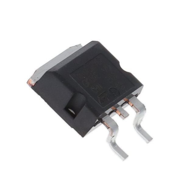
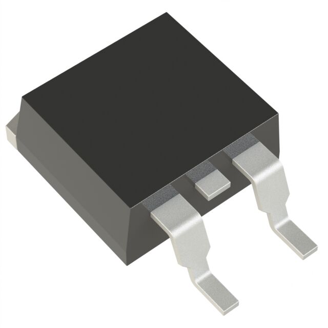
The STB26N60M2 is an N-Channel 600V 20A MOSFET manufactured by STMicroelectronics, housed in a D2PAK surface mount package. This device belongs to the MDmesh™ M2 series and is classified as Active product status. The part is RoHS3 compliant with unlimited moisture sensitivity level (MSL 1).
Substitute parts are identified when equivalent electrical performance and mechanical compatibility are required due to component availability, design optimization, or supply chain considerations. The substitute parts listed maintain the same voltage rating, package type, and surface mount configuration while offering alternative current ratings and on-resistance characteristics.
Substiute Parts
Key Parameters
| Parameter | Value | Unit |
|---|---|---|
| Drain to Source Voltage (Vdss) | 600 | V |
| Continuous Drain Current (Id) @ 25°C | 20 | A (Tc) |
| On-Resistance (Rds On Max) @ 10A, 10V | 165 | mOhm |
| Gate Threshold Voltage (Vgs(th) Max) @ 250µA | 4 | V |
| Gate Charge (Qg Max) @ 10V | 34 | nC |
| Power Dissipation (Max) | 169 | W (Tc) |
| Operating Temperature Range | -55 to 150 | °C (TJ) |
| Package Type | D2PAK (TO-263-3) | Surface Mount |
| RoHS Status | ROHS3 Compliant | - |
Substitute Part Grouping Explanation
Substitute parts for the STB26N60M2 are qualified based on the following critical parameters that determine functional equivalence:
Voltage Rating Equivalence: All substitute parts maintain the 600V Drain to Source Voltage (Vdss) rating, ensuring compatibility in high-voltage switching applications.
Package Compatibility: All substitute parts use the D2PAK (TO-263-3) surface mount package with identical pinout and thermal characteristics, allowing direct board-level replacement without layout modifications.
Current Rating Tolerance: Substitute parts are selected within the range of 18A to 23.8A continuous drain current, providing equivalent or superior current handling capability compared to the 20A rating of the primary part.
On-Resistance Characteristics: Substitute parts maintain on-resistance values between 160mOhm and 180mOhm at 10V gate drive, ensuring comparable switching losses and thermal performance.
Gate Drive Voltage: All parts operate with 10V maximum gate drive voltage, maintaining consistency with existing gate driver circuits.
Temperature Range: All parts support the -55°C to 150°C operating temperature range, ensuring thermal compatibility across industrial and automotive applications.
Compliance Standards: All parts are RoHS3 compliant with MSL 1 rating and REACH unaffected status, meeting regulatory requirements for electronics manufacturing.
Parameter Comparison
| Parameter | STB26N60M2 (Main) | IPB60R160C6ATMA1 | IPB60R180P7ATMA1 | Unit |
|---|---|---|---|---|
| Manufacturer | STMicroelectronics | Infineon Technologies | Infineon Technologies | - |
| Series | MDmesh™ M2 | CoolMOS™ C6 | CoolMOS™ P7 | - |
| Product Status | Active | Not For New Designs | Active | - |
| Vdss (Drain to Source Voltage) | 600 | 600 | 600 | V |
| Id (Continuous Drain Current) @ 25°C | 20 | 23.8 | 18 | A (Tc) |
| Rds On (Max) @ 10V | 165 @ 10A | 160 @ 11.3A | 180 @ 5.6A | mOhm |
| Vgs(th) (Max) @ Specified Id | 4 @ 250µA | 3.5 @ 750µA | 4 @ 280µA | V |
| Gate Charge (Qg Max) @ 10V | 34 | 75 | 25 | nC |
| Vgs (Max) | ±25 | ±20 | ±20 | V |
| Input Capacitance (Ciss Max) | 1360 @ 100V | 1660 @ 100V | 1081 @ 400V | pF |
| Power Dissipation (Max) | 169 | 176 | 72 | W (Tc) |
| Operating Temperature Range | -55 to 150 | -55 to 150 | -55 to 150 | °C (TJ) |
| Package Type | D2PAK (TO-263-3) | D2PAK (TO-263-3) | D2PAK (TO-263-3) | - |
| Mounting Type | Surface Mount | Surface Mount | Surface Mount | - |
| RoHS Status | ROHS3 Compliant | ROHS3 Compliant | ROHS3 Compliant | - |
| MSL Rating | 1 (Unlimited) | 1 (Unlimited) | 1 (Unlimited) | - |
| REACH Status | REACH Unaffected | REACH Unaffected | REACH Unaffected | - |
Engineering Selection Recommendations
STB26N60M2 (Primary Selection)
The STB26N60M2 is the recommended primary selection for new designs. This part maintains Active product status, indicating full manufacturer support and continued availability. The device offers balanced performance with 20A continuous drain current, 165mOhm on-resistance, and 34nC gate charge. The ±25V maximum gate voltage specification provides additional margin for gate drive circuit design. Current inventory of 2100 pieces supports immediate procurement requirements.
IPB60R180P7ATMA1 (Preferred Substitute)
The IPB60R180P7ATMA1 is the preferred substitute option when STB26N60M2 availability is constrained. This Infineon CoolMOS™ P7 device maintains Active product status and offers superior gate charge characteristics (25nC versus 34nC), resulting in reduced switching losses and improved efficiency. The 18A continuous drain current provides adequate performance for applications rated at or below 20A. The lower power dissipation rating (72W versus 169W) reflects optimized thermal performance. This part is suitable for direct replacement in existing designs with thermal margin verification.
IPB60R160C6ATMA1 (Alternative Substitute)
The IPB60R160C6ATMA1 is classified as Not For New Designs and is available only for legacy system support or design continuation. This CoolMOS™ C6 device offers the highest continuous drain current (23.8A) and lowest on-resistance (160mOhm), providing superior current handling and reduced conduction losses. However, the elevated gate charge (75nC) increases switching losses compared to other options. This part is suitable only for replacement in existing systems where design continuity is required.
Compliance and Regulatory Considerations
All three parts maintain RoHS3 compliance, MSL 1 rating, and REACH unaffected status, ensuring compatibility with current electronics manufacturing standards and regulatory requirements. No additional qualification is required from a compliance perspective.
Frequently Asked Questions (FAQ)
Q: Can the IPB60R180P7ATMA1 be used as a direct replacement for the STB26N60M2 in existing designs?
A: Yes. Both parts share identical 600V voltage rating, D2PAK package configuration, and -55°C to 150°C operating temperature range. The 18A continuous drain current of the IPB60R180P7ATMA1 is within the operational envelope of the 20A STB26N60M2. Thermal analysis should verify that the lower power dissipation rating (72W) does not create thermal margin issues in the specific application. Gate drive circuits require no modification as both parts operate at 10V maximum gate drive voltage.
Q: What is the significance of the "Not For New Designs" status of the IPB60R160C6ATMA1?
A: This designation indicates that Infineon has discontinued active development and marketing of this part for new applications. While the part remains available for existing designs and legacy system support, new designs should prioritize the IPB60R180P7ATMA1 or STB26N60M2 to ensure long-term supply chain stability and manufacturer support.
Q: How do gate charge differences affect circuit performance?
A: Gate charge (Qg) determines the energy required to switch the MOSFET on and off. The STB26N60M2 requires 34nC, the IPB60R180P7ATMA1 requires 25nC, and the IPB60R160C6ATMA1 requires 75nC. Lower gate charge reduces switching losses and allows faster switching transitions. Gate driver circuits must supply sufficient current to deliver the required charge within the specified switching time. Existing gate driver designs rated for 34nC or higher will accommodate the IPB60R180P7ATMA1 without modification.
Q: Are there package-level differences between the D2PAK variants?
A: All three parts use the D2PAK (TO-263-3) package with identical pinout and footprint. The supplier device package designations differ (D2PAK for STMicroelectronics, PG-TO263-3 for Infineon), but these refer to the same physical package. No PCB layout modifications are required for substitution.
Q: What thermal considerations apply when substituting parts?
A: The STB26N60M2 and IPB60R160C6ATMA1 are rated for 169W and 176W power dissipation respectively, while the IPB60R180P7ATMA1 is rated for 72W. The lower rating for the IPB60R180P7ATMA1 reflects its optimized design for reduced conduction losses. Thermal design calculations should account for the specific on-resistance values and application current levels. All parts share identical operating temperature range (-55°C to 150°C), so thermal management strategies remain consistent.
Q: Can the ±25V maximum gate voltage specification of the STB26N60M2 be considered an advantage over the ±20V specification of the Infineon parts?
A: The ±25V specification provides additional margin for gate drive circuit design and transient voltage spikes. However, standard gate driver circuits operate within ±20V, so this additional margin is not required for normal operation. The ±20V specification of the Infineon parts is sufficient for all standard gate drive implementations.
Q: What is the impact of input capacitance differences on switching performance?
A: Input capacitance (Ciss) affects the gate charge requirement and switching speed. The STB26N60M2 has 1360pF at 100V, the IPB60R160C6ATMA1 has 1660pF at 100V, and the IPB60R180P7ATMA1 has 1081pF at 400V. The lower input capacitance of the IPB60R180P7ATMA1 contributes to its reduced gate charge and improved switching efficiency. Existing gate driver designs will accommodate these variations without circuit modification.
Alternative Parts

SJ6012L2TP
Littelfuse Inc.
6 Alternative Parts

JMK107BBJ476MA-RE
Taiyo Yuden
10 Alternative Parts

GMK107BBJ475MA-T
Taiyo Yuden
5 Alternative Parts
SJ6020N2ARP
Littelfuse Inc.
3 Alternative Parts
SJ6025R2ATP
Littelfuse Inc.
4 Alternative Parts

2474-05L
API Delevan Inc.
1 Alternative Parts

4590R-684K
API Delevan Inc.
1 Alternative Parts

CM6560R-334
API Delevan Inc.
1 Alternative Parts

CM6460-104
API Delevan Inc.
1 Alternative Parts

5526-12
API Delevan Inc.
1 Alternative Parts