


Request Quote
(Ships tomorrow)
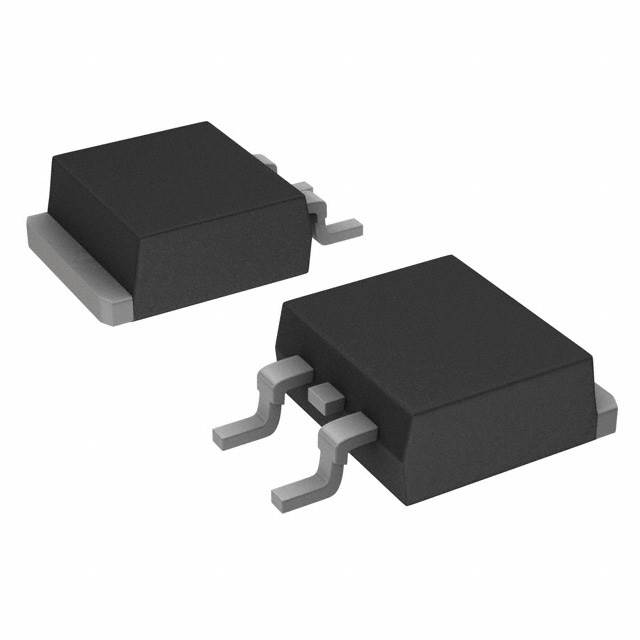
STB19NF20 N-Channel MOSFET 200V 15A D2PAK Equivalent & Substitute Parts
Part Overview
The STB19NF20 is an N-Channel MOSFET manufactured by STMicroelectronics in the MESH OVERLAY™ series, rated for 200V drain-to-source voltage with 15A continuous drain current at 25°C. The device is housed in a D2PAK (TO-263-3) surface mount package and is classified as Active product status. This component is suitable for switching applications requiring moderate current handling at 200V operating voltage. Equivalent and substitute parts are identified based on matching or exceeding critical electrical parameters while maintaining compatible packaging and thermal characteristics.
Substiute Parts
Key Parameters
| Parameter | Value | Unit |
|---|---|---|
| Drain to Source Voltage (Vdss) | 200 | V |
| Continuous Drain Current (Id) @ 25°C | 15 | A (Tc) |
| On-State Resistance (Rds On) @ 7.5A, 10V | 160 | mOhm |
| Gate Threshold Voltage (Vgs(th)) @ 250µA | 4 | V |
| Gate Charge (Qg) @ 10V | 24 | nC |
| Power Dissipation (Max) | 90 | W (Tc) |
| Operating Temperature Range | -55 to 150 | °C (TJ) |
| Package Type | D2PAK (TO-263-3) | Surface Mount |
Substitute Part Grouping Explanation
Substitute parts for the STB19NF20 are grouped based on the following critical electrical and mechanical parameters:
Primary Substitution Criteria:
- Drain-to-Source Voltage (Vdss): 200V minimum
- Continuous Drain Current (Id): 15A or greater at 25°C
- Package Type: D2PAK (TO-263-3) surface mount configuration
- On-State Resistance (Rds On): Lower or equivalent values preferred for thermal performance
- Operating Temperature Range: Minimum -55°C to 150°C
Substitution Groups:
Group 1 - Direct Equivalents (Higher Current Rating): Parts with Id ≥ 15A, Vdss = 200V, and improved thermal characteristics. These include FQB19N20TM (19.4A), IRF640NSTRLPBF (18A), IRF640SPBF (18A), IRF640STRLPBF (18A), and IRF640STRRPBF (18A).
Group 2 - Reduced Current Variants (Obsolete/Lower Performance): Parts with Id < 15A and Vdss = 200V. These include IRF630NSTRLPBF (9.3A), IRF630SPBF (9A), IRF630STRLPBF (9A), and IRF630STRRPBF (9A). These are suitable only when current requirements are lower than 15A.
Group 3 - Alternative Package Variants: RCJ160N20TL (16A) in LPTS package, functionally equivalent but with different mechanical footprint.
Parameter Comparison
| Part Number | Manufacturer | Vdss (V) | Id @ 25°C (A) | Rds On (mOhm) | Qg (nC) | Power Diss. (W) | Temp Range (°C) | Status |
|---|---|---|---|---|---|---|---|---|
| STB19NF20 | STMicroelectronics | 200 | 15 | 160 @ 7.5A | 24 @ 10V | 90 (Tc) | -55 to 150 | Active |
| FQB19N20TM | onsemi | 200 | 19.4 | 150 @ 9.7A | 40 @ 10V | 140 (Tc) | -55 to 150 | Active |
| IRF630NSTRLPBF | Infineon | 200 | 9.3 | 300 @ 5.4A | 35 @ 10V | 82 (Tc) | -55 to 175 | Obsolete |
| IRF630SPBF | Vishay Siliconix | 200 | 9 | 400 @ 5.4A | 43 @ 10V | 74 (Tc) | -55 to 150 | Active |
| IRF630STRLPBF | Vishay Siliconix | 200 | 9 | 400 @ 5.4A | 43 @ 10V | 74 (Tc) | -55 to 150 | Active |
| IRF630STRRPBF | Vishay Siliconix | 200 | 9 | 400 @ 5.4A | 43 @ 10V | 74 (Tc) | -55 to 150 | Active |
| IRF640NSTRLPBF | Infineon | 200 | 18 | 150 @ 11A | 67 @ 10V | 150 (Tc) | -55 to 175 | Active |
| IRF640SPBF | Vishay Siliconix | 200 | 18 | 180 @ 11A | 70 @ 10V | 130 (Tc) | -55 to 150 | Active |
| IRF640STRLPBF | Vishay Siliconix | 200 | 18 | 180 @ 11A | 70 @ 10V | 130 (Tc) | -55 to 150 | Active |
| IRF640STRRPBF | Vishay Siliconix | 200 | 18 | 180 @ 11A | 70 @ 10V | 130 (Tc) | -55 to 150 | Active |
| RCJ160N20TL | Rohm Semiconductor | 200 | 16 | 180 @ 8A | 26 @ 10V | 40 (Tc) | -55 to 150 | Active |
Engineering Selection Recommendations
For Direct Replacement (Active Status, Matching Performance):
FQB19N20TM (onsemi) is the primary equivalent substitute. It exceeds the STB19NF20 in continuous drain current (19.4A vs. 15A) and provides superior on-state resistance (150mOhm vs. 160mOhm). Both devices are Active status and ROHS3 compliant. The FQB19N20TM operates within the same temperature range (-55°C to 150°C) and uses identical D2PAK packaging. Higher gate charge (40nC vs. 24nC) requires consideration in gate drive circuit design.
For Higher Current Applications (Active Status):
IRF640NSTRLPBF, IRF640SPBF, IRF640STRLPBF, and IRF640STRRPBF provide 18A continuous drain current with 200V Vdss rating. These devices offer improved thermal performance (130-150W power dissipation) compared to the STB19NF20 (90W). All are Active status with ROHS3 compliance. IRF640NSTRLPBF extends operating temperature to 175°C. On-state resistance ranges from 150-180mOhm, comparable to the main part.
For Lower Current Applications (Reduced Performance):
IRF630 variants (NSTRLPBF, SPBF, STRLPBF, STRRPBF) are suitable only when application current requirements are below 9.3A. IRF630NSTRLPBF is Obsolete status and should be avoided for new designs. Remaining IRF630 variants are Active but exhibit higher on-state resistance (300-400mOhm) and lower power dissipation (74-82W).
For Alternative Packaging (Active Status):
RCJ160N20TL (Rohm Semiconductor) provides 16A continuous current at 200V with LPTS package configuration. This part is suitable when mechanical footprint differs from standard D2PAK. Gate charge is lower (26nC vs. 24nC), reducing gate drive requirements.
Compliance Considerations:
All recommended substitutes are ROHS3 compliant. STB19NF20 and most substitutes are REACH Unaffected. IRF630SPBF and IRF640SPBF are REACH Affected. Verify REACH compliance requirements for end-application jurisdiction before selection.
Frequently Asked Questions (FAQ)
Q1: Can IRF630 series parts replace STB19NF20 in all applications?
No. IRF630 variants (9A to 9.3A rating) are suitable only for applications requiring less than 9A continuous drain current. The STB19NF20 is rated for 15A, making IRF630 parts unsuitable for higher current designs. IRF630NSTRLPBF is Obsolete and should not be used in new designs.
Q2: What is the difference between FQB19N20TM and STB19NF20?
FQB19N20TM exceeds STB19NF20 specifications in continuous drain current (19.4A vs. 15A) and on-state resistance (150mOhm vs. 160mOhm). Gate charge is higher (40nC vs. 24nC), requiring gate drive circuit verification. Both operate at 200V Vdss and use D2PAK packaging. FQB19N20TM is the preferred direct equivalent.
Q3: Are IRF640 parts pin-compatible with STB19NF20?
Yes. All IRF640 variants (NSTRLPBF, SPBF, STRLPBF, STRRPBF) use D2PAK (TO-263-3) packaging with identical pin configuration. Electrical parameters differ: IRF640 series provides 18A continuous current versus 15A for STB19NF20. Higher gate charge (67-70nC vs. 24nC) must be evaluated in gate drive design.
Q4: What packaging options are available for 200V 15A+ MOSFETs?
Standard D2PAK (TO-263-3) is available across all recommended substitutes. RCJ160N20TL offers LPTS package as an alternative. Verify mechanical footprint compatibility with PCB layout before selection.
Q5: Which substitute has the lowest on-state resistance?
FQB19N20TM and IRF640NSTRLPBF both provide 150mOhm on-state resistance, matching or exceeding STB19NF20 (160mOhm). Lower on-state resistance reduces conduction losses and heat generation in switching applications.
Q6: Are there Active status alternatives to the Obsolete IRF630NSTRLPBF?
Yes. IRF630SPBF, IRF630STRLPBF, and IRF630STRRPBF are Active status variants with identical electrical specifications (9A, 200V). These are suitable only for applications with current requirements below 9A. For 15A+ applications, use FQB19N20TM or IRF640 series.
Q7: What is the impact of higher gate charge on circuit design?
Higher gate charge (40nC for FQB19N20TM vs. 24nC for STB19NF20) requires increased gate drive current or longer switching times. Gate drive circuit must supply sufficient current to charge the gate within acceptable switching frequency. Verify gate driver specifications before substitution.
Q8: Can RCJ160N20TL be used as a direct PCB replacement?
No. RCJ160N20TL uses LPTS package instead of D2PAK. Mechanical footprint and pin layout differ, requiring PCB redesign. Electrical parameters are compatible (16A, 200V, -55°C to 150°C).
Q9: Which substitutes maintain the same operating temperature range as STB19NF20?
FQB19N20TM, IRF630 series, IRF640SPBF, IRF640STRLPBF, IRF640STRRPBF, and RCJ160N20TL all operate from -55°C to 150°C. IRF640NSTRLPBF extends to 175°C maximum junction temperature.
Q10: What is the difference between Cut Tape and Tape & Reel packaging?
Cut Tape (CT) and Digi-Reel® are suitable for manual assembly or small-volume production. Tape & Reel (TR) packaging is optimized for automated pick-and-place assembly in high-volume manufacturing. Electrical specifications are identical; packaging format affects assembly process only.
Alternative Parts

SJ6012L2TP
Littelfuse Inc.
6 Alternative Parts

JMK107BBJ476MA-RE
Taiyo Yuden
10 Alternative Parts

GMK107BBJ475MA-T
Taiyo Yuden
5 Alternative Parts
SJ6020N2ARP
Littelfuse Inc.
3 Alternative Parts
SJ6025R2ATP
Littelfuse Inc.
4 Alternative Parts

2474-05L
API Delevan Inc.
1 Alternative Parts

4590R-684K
API Delevan Inc.
1 Alternative Parts

CM6560R-334
API Delevan Inc.
1 Alternative Parts

CM6460-104
API Delevan Inc.
1 Alternative Parts

5526-12
API Delevan Inc.
1 Alternative Parts