


Request Quote
(Ships tomorrow)
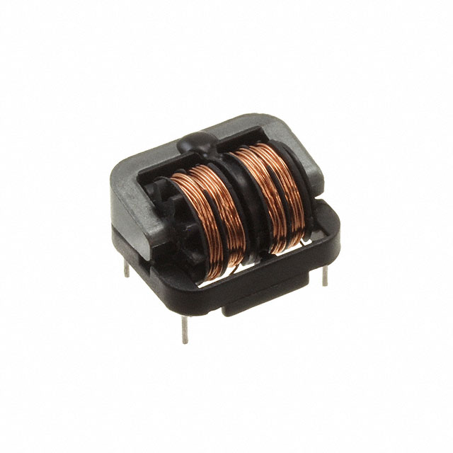
SS11V-08083-CH Common Mode Choke Equivalent & Substitute Parts
Part Overview
The SS11V-08083-CH is a 2-line common mode choke manufactured by KEMET, rated for 8.3 mH inductance at 1 kHz with 800 mA maximum current capacity and 740 mOhm DC resistance. This through-hole component operates across a temperature range of -25°C to 120°C and is rated for 250V AC. The part is ROHS3 compliant and currently in active production status with 911 units in stock.
Equivalent and substitute parts are identified when design requirements allow for variations in inductance values, frequency ratings, DC resistance, physical dimensions, or operating temperature ranges while maintaining compatibility with the 2-line through-hole configuration and 800 mA current rating.
Substiute Parts
Key Parameters
| Parameter | Value | Unit |
|---|---|---|
| Inductance @ Frequency | 8.3 mH @ 1 kHz | mH |
| Current Rating (Max) | 800 | mA |
| DC Resistance (Max) | 740 | mOhm |
| Voltage Rating - AC | 250 | V |
| Operating Temperature | -25°C ~ 120°C | °C |
| Number of Lines | 2 | Lines |
| Mounting Type | Through Hole | |
| Package / Case | Vertical, 4 PC Pin | |
| RoHS Status | ROHS3 Compliant |
Substitute Part Grouping Explanation
Substitution eligibility for the SS11V-08083-CH is determined by the following criteria:
Critical Parameters (Must Match):
- Number of Lines: 2
- Mounting Type: Through Hole
- Current Rating (Max): 800 mA
- Voltage Rating - AC: 250 V
- Package / Case: Vertical, 4 PC Pin
- RoHS Status: ROHS3 Compliant
Variable Parameters (Allowed to Differ):
- Inductance @ Frequency: Substitutes may operate at different frequency ratings (10 kHz vs. 1 kHz) with inductance values ranging from 8.2 mH to 68 mH
- DC Resistance (Max): Range from 600 mOhm to 880 mOhm
- Operating Temperature: Range from -25°C to 130°C (upper limit may extend beyond main part)
- Physical Dimensions: Variations in length, width, and height permitted within through-hole form factor
- Series Designation: Different KEMET series (SSHB10H, SSHB21H, SSHB21HS, SSR10H, SSR10HS, SSR10VS, SSR21NH)
Substitutes are grouped by inductance value proximity and DC resistance characteristics to facilitate selection based on circuit requirements.
Parameter Comparison
| Part Number | Inductance @ Frequency | Current Rating (Max) | DC Resistance (Max) | Voltage Rating - AC | Operating Temperature | Mounting Type | RoHS Status | Inventory |
|---|---|---|---|---|---|---|---|---|
| SS11V-08083-CH | 8.3 mH @ 1 kHz | 800 mA | 740 mOhm | 250 V | -25°C ~ 120°C | Through Hole | ROHS3 | 911 Pcs |
| SSHB10H-08082 | 8.2 mH @ 10 kHz | 800 mA | 640 mOhm | 250 V | -25°C ~ 130°C | Through Hole | ROHS3 | 891 Pcs |
| SSHB10H-R08194 | 19.4 mH @ 10 kHz | 800 mA | 640 mOhm | 250 V | -25°C ~ 120°C | Through Hole | ROHS3 | 899 Pcs |
| SSHB21H-08262 | 26.2 mH @ 10 kHz | 800 mA | 880 mOhm | 250 V | -25°C ~ 120°C | Through Hole | ROHS3 | 948 Pcs |
| SSHB21H-R08540 | 54 mH @ 10 kHz | 800 mA | 880 mOhm | 250 V | -25°C ~ 120°C | Through Hole | ROHS3 | 867 Pcs |
| SSHB21HS-08200 | 20 mH @ 10 kHz | 800 mA | 780 mOhm | 250 V | -25°C ~ 120°C | Through Hole | ROHS3 | 1129 Pcs |
| SSHB21HS-R08410 | 41 mH @ 10 kHz | 800 mA | 780 mOhm | 250 V | -25°C ~ 120°C | Through Hole | ROHS3 | 1174 Pcs |
| SSR10H-08220 | 22 mH @ 10 kHz | 800 mA | 650 mOhm | 250 V | -25°C ~ 120°C | Through Hole | ROHS3 | 1278 Pcs |
| SSR10HS-08180 | 18 mH @ 10 kHz | 800 mA | 600 mOhm | 250 V | -25°C ~ 120°C | Through Hole | ROHS3 | 1119 Pcs |
| SSR10VS-08180 | 18 mH @ 10 kHz | 800 mA | 600 mOhm | 250 V | -25°C ~ 120°C | Through Hole | ROHS3 | 963 Pcs |
| SSR21NH-M08680 | 68 mH @ 10 kHz | 800 mA | 800 mOhm | 250 V | -25°C ~ 120°C | Through Hole | ROHS3 | 1018 Pcs |
Engineering Selection Recommendations
All listed substitute parts maintain ROHS3 compliance and active product status, ensuring regulatory alignment and long-term availability. Selection among substitutes depends on circuit-specific inductance requirements and DC resistance tolerance.
For applications requiring inductance values closest to the main part (8.3 mH): SSHB10H-08082 provides 8.2 mH at 10 kHz with lower DC resistance (640 mOhm vs. 740 mOhm) and extended operating temperature range to 130°C.
For applications tolerating moderate inductance increases (15-25 mH range): SSHB21HS-08200 (20 mH) and SSR10H-08220 (22 mH) offer inductance values within this band with DC resistance values near the main part specification.
For applications requiring higher inductance values (40+ mH): SSHB21HS-R08410 (41 mH) and SSR21NH-M08680 (68 mH) provide significantly elevated inductance with DC resistance ranging from 780 mOhm to 800 mOhm.
All substitutes maintain the 800 mA current rating, 250V AC voltage rating, 2-line configuration, through-hole mounting, and vertical 4-pin package format of the main part.
Frequently Asked Questions (FAQ)
Q: Can SSHB10H-08082 be used as a direct replacement for SS11V-08083-CH?
A: SSHB10H-08082 is compatible from an electrical and mechanical standpoint. Both parts share 800 mA current rating, 250V AC voltage rating, 2-line through-hole configuration, and ROHS3 compliance. The inductance difference is minimal (8.2 mH vs. 8.3 mH), though measured at different frequencies (10 kHz vs. 1 kHz). DC resistance is lower (640 mOhm vs. 740 mOhm), and operating temperature range extends to 130°C. Physical dimensions differ slightly.
Q: What is the significance of the frequency rating difference (1 kHz vs. 10 kHz)?
A: Inductance values are frequency-dependent. The main part specifies 8.3 mH at 1 kHz, while most substitutes specify inductance at 10 kHz. These measurements reflect the component behavior at different operating frequencies. Circuit design must account for the frequency at which inductance is specified.
Q: Are there dimensional constraints when selecting a substitute?
A: Yes. The main part measures 0.866" L x 0.571" W x 0.886" H (22.00mm x 14.50mm x 22.50mm). Substitutes vary in dimensions. For example, SSHB21H series parts are larger (1.024" L x 0.906" W x 0.610" H), while SSR10HS parts are smaller (0.531" H). PCB layout and enclosure space must accommodate the selected substitute's physical footprint.
Q: What is the impact of DC resistance variation among substitutes?
A: DC resistance ranges from 600 mOhm (SSR10HS-08180, SSR10VS-08180) to 880 mOhm (SSHB21H-08262, SSHB21H-R08540). Higher DC resistance increases power dissipation and heat generation at rated current. Lower DC resistance reduces losses. Circuit thermal design and efficiency requirements determine acceptable DC resistance values.
Q: Do all substitutes maintain the same operating temperature range?
A: No. The main part operates from -25°C to 120°C. SSHB10H-08082 extends to 130°C. All other substitutes match the -25°C to 120°C range. Applications requiring operation above 120°C must use SSHB10H-08082.
Q: Is the 4-pin vertical package consistent across all parts?
A: Yes. All listed parts use vertical 4-pin package configuration with through-hole mounting, ensuring PCB footprint compatibility.
Q: How should inductance value selection be approached?
A: Inductance selection depends on circuit filtering requirements. The main part at 8.3 mH suits specific EMI suppression applications. Substitutes with higher inductance (20-68 mH) provide greater filtering but increase component size and DC resistance. Lower inductance substitutes (8.2 mH) maintain similar filtering characteristics with reduced losses.
Alternative Parts

SJ6012L2TP
Littelfuse Inc.
6 Alternative Parts

JMK107BBJ476MA-RE
Taiyo Yuden
10 Alternative Parts

GMK107BBJ475MA-T
Taiyo Yuden
5 Alternative Parts
SJ6020N2ARP
Littelfuse Inc.
3 Alternative Parts
SJ6025R2ATP
Littelfuse Inc.
4 Alternative Parts

2474-05L
API Delevan Inc.
1 Alternative Parts

4590R-684K
API Delevan Inc.
1 Alternative Parts

CM6560R-334
API Delevan Inc.
1 Alternative Parts

CM6460-104
API Delevan Inc.
1 Alternative Parts

5526-12
API Delevan Inc.
1 Alternative Parts