


Request Quote
(Ships tomorrow)
SPW35N60CFDFKSA1 Equivalent & Substitute Parts
Part Overview
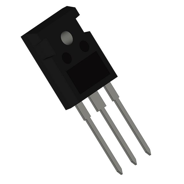
The SPW35N60CFDFKSA1 is an N-Channel 600V 34.1A MOSFET manufactured by Infineon Technologies in the CoolMOS™ series. This device is packaged in TO-247-3 through-hole configuration with a maximum power dissipation of 313W at case temperature. The part is designated as "Not For New Designs," indicating it has been superseded in Infineon's product roadmap. Identifying equivalent and substitute parts is necessary for applications requiring continued supply, design flexibility, or performance optimization within compatible electrical and mechanical parameters.
Substiute Parts
Key Parameters
| Parameter | Value | Unit |
|---|---|---|
| Drain to Source Voltage (Vdss) | 600 | V |
| Continuous Drain Current (Id) @ 25°C | 34.1 | A (Tc) |
| On-State Resistance (Rds On Max) @ Id, Vgs | 118 mOhm @ 21.6A, 10V | mOhm |
| Gate Threshold Voltage (Vgs(th) Max) @ Id | 5 | V @ 1.9mA |
| Gate Charge (Qg Max) @ Vgs | 212 | nC @ 10V |
| Maximum Gate Voltage (Vgs Max) | ±20 | V |
| Input Capacitance (Ciss Max) @ Vds | 5060 | pF @ 25V |
| Power Dissipation (Max) | 313 | W (Tc) |
| Operating Temperature Range | -55 to 150 | °C (TJ) |
| Package Type | TO-247-3 | Through Hole |
| FET Type | N-Channel | MOSFET |
| RoHS Status | ROHS3 Compliant | - |
Substitute Part Grouping Explanation
Substitution of the SPW35N60CFDFKSA1 is determined by strict alignment of the following critical parameters:
Voltage Rating Compatibility: All substitute parts must maintain a Drain to Source Voltage (Vdss) rating of 600V or higher to ensure safe operation in the original application circuit.
Current Capacity: Substitute parts must support continuous drain current (Id) at or above 34.1A at 25°C to meet or exceed the original device's current-handling capability.
On-State Resistance (Rds On): The maximum on-state resistance must not significantly exceed the original specification to prevent excessive power dissipation and thermal stress in the application.
Gate Charge (Qg): Gate charge values influence switching speed and driver circuit requirements. Substitutes with substantially lower gate charge may improve efficiency but must remain compatible with existing gate drive circuitry.
Package and Mounting: All substitutes must use TO-247-3 through-hole packaging to ensure mechanical and thermal compatibility with existing PCB layouts and heatsink arrangements.
Operating Temperature Range: Substitutes must support the full -55°C to 150°C operating temperature range to maintain reliability across all application conditions.
Compliance and Status: Substitutes with "Active" product status are preferred for new applications. RoHS3 compliance and REACH unaffected status ensure regulatory alignment.
Parameter Comparison
| Parameter | SPW35N60CFDFKSA1 | FCH104N60F | FCH110N65F-F155 | IXFH20N60 | IXFH34N65X2 | IXTH20N60 | STW33N60M2 | STW34NM60ND |
|---|---|---|---|---|---|---|---|---|
| Manufacturer | Infineon | onsemi | Fairchild | IXYS | IXYS | IXYS | STMicroelectronics | STMicroelectronics |
| Vdss (V) | 600 | 600 | 650 | 600 | 650 | 600 | 600 | 600 |
| Id @ 25°C (A) | 34.1 | 37 | 35 | 20 | 34 | 20 | 26 | 29 |
| Rds On Max (mOhm) | 118 @ 21.6A, 10V | 104 @ 18.5A, 10V | 110 @ 17.5A, 10V | 350 @ 10A, 10V | 105 @ 17A, 10V | 350 @ 10A, 10V | 125 @ 13A, 10V | 110 @ 14.5A, 10V |
| Vgs(th) Max (V) | 5 @ 1.9mA | 5 @ 250µA | 5 @ 3.5mA | 4.5 @ 4mA | 5.5 @ 2.5mA | 4.5 @ 250µA | 4 @ 250µA | 5 @ 250µA |
| Qg Max (nC) | 212 @ 10V | 139 @ 10V | 145 @ 10V | 170 @ 10V | 56 @ 10V | 170 @ 10V | 45.5 @ 10V | 80.4 @ 10V |
| Vgs Max (V) | ±20 | ±20 | ±20 | ±20 | ±30 | ±20 | ±25 | ±25 |
| Ciss Max (pF) | 5060 @ 25V | 5950 @ 100V | 4895 @ 100V | 4500 @ 25V | 3330 @ 25V | 4500 @ 25V | 1781 @ 100V | 2785 @ 50V |
| Power Dissipation Max (W) | 313 | 357 | 357 | 300 | 540 | 300 | 190 | 190 |
| Operating Temperature (°C) | -55 to 150 | -55 to 150 | -55 to 150 | -55 to 150 | -55 to 150 | -55 to 150 | -55 to 150 | -55 to 150 |
| Package | TO-247-3 | TO-247-3 | TO-247-3 | TO-247-3 | TO-247-3 | TO-247-3 | TO-247-3 | TO-247-3 |
| Product Status | Not For New Designs | Not For New Designs | Active | Active | Active | Active | Active | Active |
| RoHS Status | ROHS3 Compliant | ROHS3 Compliant | Not Specified | ROHS3 Compliant | ROHS3 Compliant | ROHS3 Compliant | ROHS3 Compliant | ROHS3 Compliant |
Engineering Selection Recommendations
Primary Substitutes for Direct Replacement:
FCH104N60F (onsemi) and FCH110N65F-F155 (Fairchild) provide the closest electrical performance match to the SPW35N60CFDFKSA1. Both devices maintain 600V or higher voltage ratings, support continuous drain currents at or above 34A, and feature comparable on-state resistance values. FCH104N60F operates at 600V with 37A continuous current and 104 mOhm on-state resistance, delivering superior current capacity and lower conduction losses. FCH110N65F-F155 provides a 650V rating with 35A continuous current and 110 mOhm on-state resistance, offering enhanced voltage margin. Both are packaged in TO-247-3 and support the full -55°C to 150°C operating range. FCH110N65F-F155 maintains Active product status, making it suitable for new designs.
Secondary Substitutes with Performance Trade-offs:
IXFH34N65X2 (IXYS) and STW34NM60ND (STMicroelectronics) offer alternative solutions with specific performance characteristics. IXFH34N65X2 delivers 650V voltage rating, 34A continuous current, and 105 mOhm on-state resistance with significantly reduced gate charge (56 nC versus 212 nC), enabling faster switching and improved efficiency. This device features Active product status and ROHS3 compliance. STW34NM60ND provides 600V rating, 29A continuous current, and 110 mOhm on-state resistance with lower gate charge (80.4 nC), supporting Active product status and full temperature range operation.
Lower Current Alternatives:
IXFH20N60 and IXTH20N60 (both IXYS) are suitable only for applications where continuous drain current requirements do not exceed 20A. These devices maintain 600V voltage rating and TO-247-3 packaging but feature higher on-state resistance (350 mOhm) and reduced power dissipation capability (300W). Both maintain Active product status and ROHS3 compliance.
Reduced Power Dissipation Alternatives:
STW33N60M2 (STMicroelectronics) supports 600V rating and 26A continuous current with 125 mOhm on-state resistance. This device exhibits significantly lower power dissipation (190W) and reduced gate charge (45.5 nC), suitable for applications with lower thermal budgets. Active product status and ROHS3 compliance are maintained.
Compliance and Regulatory Alignment:
All recommended substitutes maintain ROHS3 compliance and REACH unaffected status, ensuring regulatory alignment with the original SPW35N60CFDFKSA1. Substitutes with Active product status (FCH110N65F-F155, IXFH34N65X2, IXTH20N60, STW33N60M2, STW34NM60ND) are preferred for new design implementations. Substitutes with "Not For New Designs" status (FCH104N60F) are suitable for legacy system support and replacement applications only.
Frequently Asked Questions (FAQ)
Q: Can FCH104N60F directly replace SPW35N60CFDFKSA1 in existing designs?
A: FCH104N60F is electrically compatible with SPW35N60CFDFKSA1 for direct replacement. Both devices maintain 600V voltage rating, TO-247-3 packaging, and -55°C to 150°C operating temperature range. FCH104N60F provides superior current capacity (37A versus 34.1A) and lower on-state resistance (104 mOhm versus 118 mOhm), resulting in reduced conduction losses. Gate charge differs (139 nC versus 212 nC), which may require gate driver circuit evaluation to ensure compatibility with existing switching frequency and driver output impedance specifications.
Q: What is the primary advantage of IXFH34N65X2 over SPW35N60CFDFKSA1?
A: IXFH34N65X2 offers significantly reduced gate charge (56 nC versus 212 nC), enabling faster switching transitions and lower gate drive power consumption. The 650V voltage rating provides enhanced overvoltage margin compared to the 600V rating of SPW35N60CFDFKSA1. On-state resistance is comparable (105 mOhm versus 118 mOhm). The device maintains Active product status, making it suitable for new design implementations. Input capacitance is substantially lower (3330 pF versus 5060 pF), reducing switching losses in high-frequency applications.
Q: Are IXFH20N60 and IXTH20N60 suitable substitutes for high-current applications?
A: IXFH20N60 and IXTH20N60 are not suitable for applications requiring continuous drain currents above 20A. Both devices are rated for 20A continuous current, significantly below the SPW35N60CFDFKSA1 specification of 34.1A. These devices feature higher on-state resistance (350 mOhm versus 118 mOhm) and reduced power dissipation capability (300W versus 313W). These parts are appropriate only for lower-current applications or as substitutes in circuits where current requirements have been reduced.
Q: What is the significance of product status designation in selecting a substitute?
A: Product status indicates manufacturer support and design roadmap positioning. "Active" status indicates the manufacturer continues to support the device for new designs and maintains production and supply commitments. "Not For New Designs" status indicates the device has been superseded and may face supply constraints or discontinuation. For new design implementations, substitutes with Active status (FCH110N65F-F155, IXFH34N65X2, IXTH20N60, STW33N60M2, STW34NM60ND) are preferred. For legacy system support and replacement applications, substitutes with either status are acceptable if electrical parameters align.
Q: How does gate charge affect circuit performance when substituting MOSFETs?
A: Gate charge (Qg) determines the total charge required to switch the MOSFET from off to on state. Lower gate charge reduces switching time and gate drive power consumption, improving overall circuit efficiency. SPW35N60CFDFKSA1 specifies 212 nC gate charge, while substitutes range from 45.5 nC (STW33N60M2) to 212 nC (FCH104N60F). Substitutes with significantly lower gate charge (IXFH34N65X2 at 56 nC, STW33N60M2 at 45.5 nC) enable faster switching and reduced driver stress. Gate driver circuits must be evaluated to ensure adequate output current capability for the selected gate charge specification.
Q: Is the 650V rating of FCH110N65F-F155 and IXFH34N65X2 compatible with 600V applications?
A: Yes, devices with 650V voltage rating are fully compatible with 600V applications. The higher voltage rating provides additional overvoltage margin and enhanced reliability under transient voltage conditions. No circuit modifications are required. The 650V rating ensures the device remains within safe operating limits when subjected to voltage spikes or transient overvoltages that may exceed the nominal 600V supply voltage.
Q: What thermal considerations apply when substituting MOSFETs with different power dissipation ratings?
A: Power dissipation rating indicates the maximum thermal power the device can safely dissipate at case temperature (Tc). SPW35N60CFDFKSA1 specifies 313W, while substitutes range from 190W (STW33N60M2, STW34NM60ND) to 540W (IXFH34N65X2). Substitutes with lower power dissipation ratings require more efficient thermal management or operation at reduced current levels. Substitutes with higher power dissipation ratings provide additional thermal margin. Heatsink design and thermal interface material specifications must be evaluated to ensure the selected substitute operates within safe junction temperature limits under application-specific duty cycle and ambient temperature conditions.
Q: Are all substitute parts available in the same packaging configuration?
A: Yes, all substitute parts listed are packaged in TO-247-3 through-hole configuration, ensuring mechanical and thermal compatibility with existing PCB layouts and heatsink arrangements. No modifications to mounting hardware, PCB footprints, or thermal interface materials are required for package compatibility.
Alternative Parts

SJ6012L2TP
Littelfuse Inc.
6 Alternative Parts

JMK107BBJ476MA-RE
Taiyo Yuden
10 Alternative Parts

GMK107BBJ475MA-T
Taiyo Yuden
5 Alternative Parts
SJ6020N2ARP
Littelfuse Inc.
3 Alternative Parts
SJ6025R2ATP
Littelfuse Inc.
4 Alternative Parts

2474-05L
API Delevan Inc.
1 Alternative Parts

4590R-684K
API Delevan Inc.
1 Alternative Parts

CM6560R-334
API Delevan Inc.
1 Alternative Parts

CM6460-104
API Delevan Inc.
1 Alternative Parts

5526-12
API Delevan Inc.
1 Alternative Parts