


Request Quote
(Ships tomorrow)
SPU07N60C3BKMA1 Equivalent & Substitute Parts
Part Overview
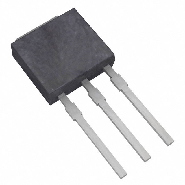
The SPU07N60C3BKMA1 is an N-Channel 650V 7.3A MOSFET manufactured by Infineon Technologies in the CoolMOS™ series, housed in a TO-251-3 (IPAK) through-hole package. This component is classified as obsolete, necessitating identification of functionally equivalent alternatives from active product lines. Substitute parts must maintain electrical compatibility across voltage rating, current capacity, on-resistance characteristics, and thermal performance parameters while preserving the TO-251-3 package form factor for direct board-level replacement.
Substiute Parts
Key Parameters
| Parameter | SPU07N60C3BKMA1 | Unit |
|---|---|---|
| Drain to Source Voltage (Vdss) | 650 | V |
| Continuous Drain Current (Id) @ 25°C | 7.3 | A |
| On-Resistance (Rds On Max) @ Id, Vgs | 600 mOhm @ 4.6A, 10V | mOhm |
| Gate Threshold Voltage (Vgs(th) Max) @ Id | 3.9 | V @ 350µA |
| Gate Charge (Qg Max) @ Vgs | 27 | nC @ 10V |
| Power Dissipation (Max) | 83 | W |
| Operating Temperature Range | -55 to 150 | °C |
| Package Type | TO-251-3 (IPAK) | — |
| Mounting Type | Through Hole | — |
| RoHS Status | ROHS3 Compliant | — |
Substitute Part Grouping Explanation
Substitution of the SPU07N60C3BKMA1 is determined by the following critical parameters:
Voltage Rating Compatibility: The main part operates at 650V Vdss. All substitute parts operate at 600V Vdss, representing a 50V reduction in maximum drain-source voltage. This reduction is acceptable in applications where the operating voltage margin does not require the full 650V rating.
Current Rating Compatibility: The main part is rated for 7.3A continuous drain current. Substitute parts range from 5A to 10A, encompassing the original specification. Parts rated at or above 7.3A provide direct current compatibility; parts below this threshold are suitable only for applications with reduced current requirements.
On-Resistance (Rds On) Characteristics: The main part specifies 600 mOhm maximum on-resistance. Substitute parts range from 550 mOhm to 900 mOhm. Lower on-resistance values indicate improved efficiency and reduced power dissipation; higher values indicate increased conduction losses.
Package and Mounting: All substitute parts maintain the TO-251-3 (IPAK) through-hole package form factor, ensuring mechanical and electrical compatibility with existing PCB layouts.
Product Status and Compliance: Substitute parts are selected from active product lines with current manufacturing status, ensuring long-term availability and supply chain continuity. All parts maintain ROHS3 compliance and identical MSL ratings.
Parameter Comparison
| Parameter | SPU07N60C3BKMA1 | STU10N60M2 | STU10NM60N | STU7NM60N | STU9N60M2 | Unit |
|---|---|---|---|---|---|---|
| Manufacturer | Infineon | STMicroelectronics | STMicroelectronics | STMicroelectronics | STMicroelectronics | — |
| Vdss | 650 | 600 | 600 | 600 | 600 | V |
| Id @ 25°C | 7.3 | 7.5 | 10 | 5 | 5.5 | A |
| Rds On (Max) | 600 @ 4.6A, 10V | 600 @ 3A, 10V | 550 @ 4A, 10V | 900 @ 2.5A, 10V | 780 @ 3A, 10V | mOhm |
| Vgs(th) (Max) | 3.9 @ 350µA | 4 @ 250µA | 4 @ 250µA | 4 @ 250µA | 4 @ 250µA | V |
| Qg (Max) @ 10V | 27 | 13.5 | 19 | 14 | 10 | nC |
| Power Dissipation (Max) | 83 | 85 | 70 | 45 | 60 | W |
| Operating Temperature | -55 to 150 | -55 to 150 | -55 to 150 | —150 | —150 | °C |
| Package | TO-251-3 (IPAK) | TO-251 (IPAK) | TO-251 (IPAK) | TO-251 (IPAK) | TO-251 (IPAK) | — |
| Product Status | Obsolete | Obsolete | Active | Active | Active | — |
| RoHS Status | ROHS3 | ROHS3 | ROHS3 | ROHS3 | ROHS3 | — |
Engineering Selection Recommendations
Primary Recommendation: STU10NM60N
The STU10NM60N is the preferred substitute for the SPU07N60C3BKMA1. This part is classified as active product status, ensuring current manufacturing and long-term supply availability. It provides 10A continuous drain current, exceeding the original 7.3A specification, with improved on-resistance of 550 mOhm compared to the original 600 mOhm. The reduced gate charge of 19 nC facilitates faster switching characteristics. The 600V Vdss rating is suitable for applications where the 50V voltage margin reduction from 650V does not impact circuit performance. Power dissipation is rated at 70W, providing adequate thermal headroom for most applications.
Secondary Recommendation: STU9N60M2
The STU9N60M2 serves as an alternative for applications requiring current ratings between 5.5A and 7.3A. This part offers the lowest gate charge specification at 10 nC, enabling superior switching performance in high-frequency applications. On-resistance of 780 mOhm is higher than the original specification, resulting in increased conduction losses. Product status is active, ensuring supply continuity. Power dissipation is rated at 60W.
Tertiary Recommendation: STU10N60M2
The STU10N60M2 provides 7.5A continuous drain current with matching 600 mOhm on-resistance to the original part. However, this part is classified as obsolete, limiting its suitability for new designs requiring long-term component availability. It may be considered only for legacy system maintenance where existing inventory is available.
Not Recommended: STU7NM60N
The STU7NM60N is rated for only 5A continuous drain current, falling below the original 7.3A specification. This part is suitable only for applications with reduced current requirements and should not be selected as a direct substitute for the SPU07N60C3BKMA1 in circuits designed for the full 7.3A rating.
Frequently Asked Questions (FAQ)
Q: Can the STU10NM60N directly replace the SPU07N60C3BKMA1 on the PCB?
A: Yes. Both parts use the TO-251-3 (IPAK) through-hole package with identical pinout and mechanical dimensions. No PCB modifications are required for physical installation.
Q: What is the impact of the 50V reduction in Vdss from 650V to 600V?
A: The voltage reduction affects maximum operating voltage margin. Applications operating below 600V experience no functional impact. Applications requiring operation above 600V or with minimal voltage headroom must retain the original 650V-rated part or redesign the circuit for the lower voltage rating.
Q: Why does the STU10NM60N have lower power dissipation (70W) than the original part (83W) despite higher current rating?
A: Power dissipation is determined by both current capacity and on-resistance characteristics. The STU10NM60N features improved on-resistance (550 mOhm vs. 600 mOhm), resulting in lower conduction losses and reduced overall power dissipation despite the higher current rating.
Q: Is the STU10N60M2 suitable for new designs?
A: No. The STU10N60M2 is classified as obsolete. While it may be available from existing inventory, new designs should specify the STU10NM60N (active status) to ensure long-term supply chain continuity and manufacturing support.
Q: What does gate charge (Qg) represent, and why is it lower in substitute parts?
A: Gate charge represents the total charge required to switch the MOSFET from off to on state. Lower gate charge values enable faster switching transitions and reduced switching losses in high-frequency applications. The substitute parts exhibit lower gate charge due to improved semiconductor process technology in the MDmesh™ II series compared to the original CoolMOS™ design.
Q: Can the STU7NM60N be used in applications requiring 7.3A continuous current?
A: No. The STU7NM60N is rated for only 5A continuous drain current. Operating this part at 7.3A exceeds its maximum specification and results in thermal stress, reduced component lifetime, and potential failure. This part is suitable only for applications with current requirements at or below 5A.
Q: Are all substitute parts RoHS3 compliant?
A: Yes. All substitute parts listed maintain ROHS3 compliance and identical Moisture Sensitivity Level (MSL) ratings of 1 (Unlimited), ensuring compatibility with standard manufacturing and storage procedures.
Alternative Parts

SJ6012L2TP
Littelfuse Inc.
6 Alternative Parts

JMK107BBJ476MA-RE
Taiyo Yuden
10 Alternative Parts

GMK107BBJ475MA-T
Taiyo Yuden
5 Alternative Parts
SJ6020N2ARP
Littelfuse Inc.
3 Alternative Parts
SJ6025R2ATP
Littelfuse Inc.
4 Alternative Parts

2474-05L
API Delevan Inc.
1 Alternative Parts

4590R-684K
API Delevan Inc.
1 Alternative Parts

CM6560R-334
API Delevan Inc.
1 Alternative Parts

CM6460-104
API Delevan Inc.
1 Alternative Parts

5526-12
API Delevan Inc.
1 Alternative Parts