


Request Quote
(Ships tomorrow)
SPM10054T-4R7M-HZ Equivalent & Substitute Parts
Part Overview
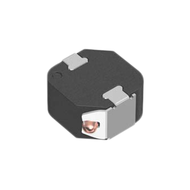
The SPM10054T-4R7M-HZ is a 4.7 µH shielded drum core wirewound inductor manufactured by TDK Corporation, rated for 14.3 A continuous current with a maximum DC resistance of 12.15 mOhm. This component is designed for surface mount applications in automotive and industrial circuits requiring high current handling with controlled inductance values.
The SPM10054T-4R7M-HZ carries a "Not For New Designs" status, indicating that TDK has transitioned this model out of active production. Finding equivalent substitute parts is necessary to maintain design continuity, ensure supply chain availability, and support existing production requirements for systems currently utilizing this inductor.
Substiute Parts
Key Parameters
| Parameter | Value | Unit |
|---|---|---|
| Inductance | 4.7 | µH |
| Inductance Tolerance | ±20% | — |
| Current Rating (Continuous) | 14.3 | A |
| Current - Saturation (Isat) | 6.6 | A |
| DC Resistance (DCR) Maximum | 12.15 | mOhm |
| Core Material | Metal | — |
| Shielding | Shielded | — |
| Operating Temperature Range | -40 to 125 | °C |
| Mounting Type | Surface Mount | — |
| Package Dimensions (L × W × H) | 10.70 × 10.00 × 5.40 | mm |
| AEC-Q200 Rated | Yes | — |
| RoHS3 Compliant | Yes | — |
Substitute Part Grouping Explanation
Substitute parts for the SPM10054T-4R7M-HZ must satisfy the following electrical and mechanical criteria:
Electrical Parameters (Critical for Substitution):
- Inductance value: 4.7 µH ±20% tolerance
- Core material: Metal (shielded construction)
- Shielding: Shielded configuration
- Operating temperature range: -40°C to 125°C minimum
- AEC-Q200 automotive qualification
Mechanical Parameters (Critical for Substitution):
- Mounting type: Surface mount
- Package dimensions: 10.70 mm L × 10.00 mm W × 5.40 mm H (maximum seated height)
- Nonstandard package classification
Performance Parameters (Compatibility Dependent):
- Current rating and saturation current must be evaluated against circuit requirements
- DC resistance affects thermal performance and must be considered for power dissipation calculations
The SPM10054T-4R7M-HZR is identified as the manufacturer-recommended substitute. While it maintains identical inductance, core material, shielding, temperature range, and physical dimensions, it exhibits different current handling characteristics (9.5 A continuous vs. 14.3 A) and DC resistance (14 mOhm vs. 12.15 mOhm maximum). These differences require circuit-level evaluation to confirm compatibility.
Parameter Comparison
| Parameter | SPM10054T-4R7M-HZ (Main) | SPM10054T-4R7M-HZR (Substitute) | Match Status |
|---|---|---|---|
| Manufacturer | TDK Corporation | TDK Corporation | Identical |
| Inductance | 4.7 µH | 4.7 µH | Identical |
| Inductance Tolerance | ±20% | ±20% | Identical |
| Current Rating (Continuous) | 14.3 A | 9.5 A | Substitute Lower |
| Current - Saturation (Isat) | 6.6 A | 12.2 A | Substitute Higher |
| DC Resistance (DCR) Maximum | 12.15 mOhm | 14 mOhm | Substitute Higher |
| Core Material | Metal | Metal | Identical |
| Shielding | Shielded | Shielded | Identical |
| Operating Temperature Range | -40 to 125°C | -40 to 125°C | Identical |
| Mounting Type | Surface Mount | Surface Mount | Identical |
| Package Dimensions (L × W × H) | 10.70 × 10.00 × 5.40 mm | 10.70 × 10.00 × 5.40 mm | Identical |
| AEC-Q200 Rated | Yes | Yes | Identical |
| RoHS3 Compliant | Yes | Yes | Identical |
| Product Status | Not For New Designs | Active | Substitute Active |
Engineering Selection Recommendations
Primary Substitute: SPM10054T-4R7M-HZR
The SPM10054T-4R7M-HZR is the manufacturer-recommended substitute and maintains full compliance with AEC-Q200 automotive qualification and RoHS3 requirements. It preserves the critical electrical parameters: 4.7 µH inductance, metal shielded core construction, and identical operating temperature range (-40°C to 125°C).
The substitute part carries Active product status, ensuring long-term supply chain availability compared to the "Not For New Designs" classification of the original part.
Compatibility Considerations:
The SPM10054T-4R7M-HZR exhibits a reduced continuous current rating (9.5 A vs. 14.3 A) and increased DC resistance (14 mOhm vs. 12.15 mOhm maximum). These differences must be evaluated against the specific circuit application:
- If the circuit operates at continuous currents exceeding 9.5 A, the substitute part may not be suitable without circuit redesign.
- The increased DC resistance will result in higher power dissipation and thermal generation. Thermal analysis of the application is required to confirm acceptable operating conditions.
- The substitute part exhibits higher saturation current (12.2 A vs. 6.6 A), which may provide improved performance margin in certain transient conditions.
Both parts share identical physical dimensions and mounting characteristics, ensuring PCB layout compatibility without modification.
Frequently Asked Questions (FAQ)
Q: Can the SPM10054T-4R7M-HZR be used as a direct replacement for the SPM10054T-4R7M-HZ?
A: Physical and thermal compatibility is confirmed due to identical package dimensions and mounting type. However, electrical compatibility depends on circuit current requirements. If the application operates at continuous currents below 9.5 A, the substitute is compatible. Applications requiring the full 14.3 A rating require circuit evaluation or alternative solutions.
Q: What is the impact of the increased DC resistance in the substitute part?
A: The SPM10054T-4R7M-HZR exhibits 14 mOhm maximum DC resistance compared to 12.15 mOhm in the original part. This 1.85 mOhm increase results in higher resistive losses and thermal generation. Power dissipation increases proportionally with the square of the current. For a 9.5 A application, the thermal impact must be calculated and verified against thermal design limits.
Q: Are both parts qualified for automotive applications?
A: Yes. Both the SPM10054T-4R7M-HZ and SPM10054T-4R7M-HZR carry AEC-Q200 automotive qualification and RoHS3 compliance, confirming suitability for automotive circuit applications within their respective current ratings.
Q: What is the difference in saturation current between these parts?
A: The original part saturates at 6.6 A, while the substitute saturates at 12.2 A. Higher saturation current in the substitute part indicates improved performance margin against saturation-induced inductance collapse during transient current events. This characteristic may be advantageous in applications with current spikes or transient conditions.
Q: Are there packaging differences between these parts?
A: The original part is supplied in Tape & Reel (TR) packaging. The substitute part is available in Cut Tape (CT) and Digi-Reel® packaging options. Both maintain identical component dimensions and surface mount compatibility. Packaging selection depends on procurement and assembly process requirements.
Q: What should be verified before implementing the substitute part?
A: Verify that the application's maximum continuous current requirement does not exceed 9.5 A. Perform thermal analysis to confirm that the increased DC resistance does not cause unacceptable temperature rise. Confirm that the saturation current margin remains adequate for the application's transient current profile.
Alternative Parts

SJ6012L2TP
Littelfuse Inc.
6 Alternative Parts

JMK107BBJ476MA-RE
Taiyo Yuden
10 Alternative Parts

GMK107BBJ475MA-T
Taiyo Yuden
5 Alternative Parts
SJ6020N2ARP
Littelfuse Inc.
3 Alternative Parts
SJ6025R2ATP
Littelfuse Inc.
4 Alternative Parts

2474-05L
API Delevan Inc.
1 Alternative Parts

4590R-684K
API Delevan Inc.
1 Alternative Parts

CM6560R-334
API Delevan Inc.
1 Alternative Parts

CM6460-104
API Delevan Inc.
1 Alternative Parts

5526-12
API Delevan Inc.
1 Alternative Parts